Harmonic currents produced by non-linear electronic loads are injected in to the power system grid. The effect of injecting large magnitude of harmonic current in to the grid depends on the response of the power grid to the various injected harmonic frequencies. Depending on the response of the grid, the injected current could simply flow in to the grid harmlessly or create electrical power system resonance resulting in damaging overvoltage or overcurrent conditions. The characteristics of the system that determine the response of the grid to the power system harmonics are:
*Impedance of the system to each harmonic frequency
*Presence of any capacitor banks
*Amount of resistive loads
There are some key ideas to be understood while trying to delve in to understanding electrical power system harmonic resonance. They are:
Non-linear loads produce harmonic current which are then injected in to the power grid.
The current flowing in to the source (grid) produces voltage drop proportional to the impedance offered to that particular harmonic frequency component.
If the source inductance and capacitance form a series or parallel resonant circuit, then the injected current can cause very high current and voltage distortion.
Every system with capacitors will have a parallel resonant point. The important thing to determine is if this resonant point is close to one of the harmonic frequencies injected by the system loads.
Symptoms and characteristics of harmonic resonance
Self-correcting: Most harmonic resonance problems are usually self-correcting, meaning the resonant condition will cause enough current/voltage in the system that could either blow the fuses, fail the capacitor (thereby coming out of resonance) or other system damage that makes the system not resonant any more. Note that low level system resonance can still go unnoticed for long time and many not cause any failure that bring attention to the problem immediately.
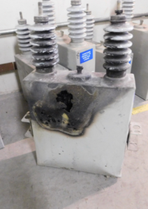
Capacitor fuse blow: Resonant condition usually result in high capacitor currents and fuse operation.
Capacitor failure: Capacitor can also be damaged due to overheating or voltage stress damage to insulating layers inside the bank.
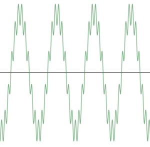
Voltage distortion: For resonant condition the distortion will be due to one or two closely spaced harmonic orders. By analyzing the current and voltage on a power quality analyzer the harmonic order that is causing the resonance can usually be identified.
Equipment failure: Low level resonance can go unnoticed for a long time. Usually the symptoms are unexplained failure of sensitive power supplies, electronic loads, transformer overheating etc.
Steady State Condition: Harmonic resonance is considered a steady state phenomenon. Though switching induced transient resonance is possible, it is dealt using a transient simulation program and usually needs different mitigation methods.
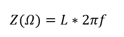
Inductive Impedance
Power system impedance is primarily inductive at the nominal frequency (50/60Hz). The impedance varies depending on the harmonic frequency. For an inductance ‘L’, the impedance Z at frequency f is given by
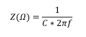
Capacitive Impedance
Power system capacitors could be power factor correction capacitors, cable capacitance, breaker capacitance etc. The impedance varies inversely depending on the harmonic frequency. For a capacitor ‘C’, the impedance Z at frequency f is given by
The impedance of inductor varies inversely with frequency. For higher order harmonics (large f), impedance will be proportionally lower.
When the system inductive impedance and capacitive reactance become equal, resonant condition can develop. It can be:
Parallel Resonance
Series Resonance
Parallel Resonance in Power System
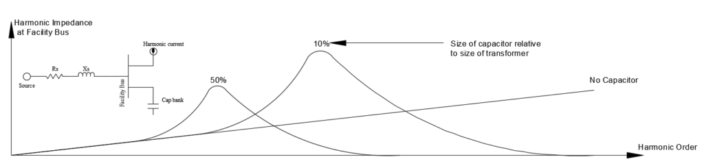
Below is a system that can drift in to parallel resonance. This could a large industrial facility where multiple low voltage substations inject harmonic current in to the medium voltage facility bus. A potential parallel resonant condition can develop between the medium or low voltage facility power factor capacitor bank and the source inductance Xs.
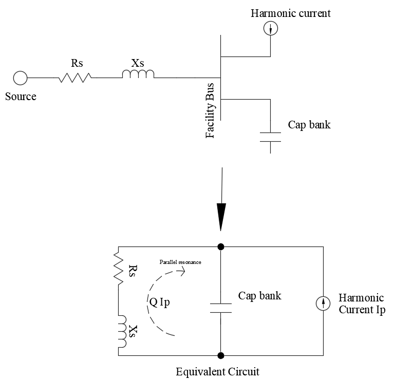
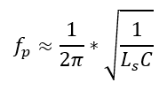
Resonant frequency is given by:
At parallel resonant frequency, the effective impedance of the circuit will become very high. Note that at resonance Xs=Xc. For the circuit shown,
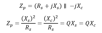
Q is known as the quality factor and determines the sharpness of the frequency response. For a distribution system the Q could be 5 and may be 30 at the secondary of a large distribution transformer. The value of Q is different for series resonant and parallel resonant circuit.
Voltage across capacitor
During parallel resonant condition, there is very high voltage on the capacitor given by.
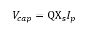
Since the Values of QXs is very high a small harmonic current (Ip) can cause large voltage to drop across the capacitor.
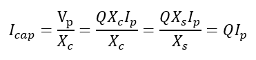
Current through capacitor
During parallel resonant condition, the current flowing in the capacitor and in the transformer, is magnified Q times the harmonic current injected (Ip).
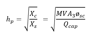
The current magnification can cause capacitor failure, transformer heating, fuse blowing. The size of the shunt capacitor bank relative to the source MVA determines the parallel resonant tuning point. The parallel resonant frequency for a system with shunt capacitor banks applied at the secondary of a power transformer is given by:
Where
hp is the order of the parallel resonant frequency
MVA3øsc is the three-phase short circuit MVA
Xs is the system short circuit reactance
Xc is the equivalent wye reactance of the capacitor bank
Qcap is the capacitor bank size in MVAR
MVA3øsc is the effective short circuit MVA at the point of interest. For most applications a quick estimate of the MVA3øsc can be made by identifying the upstream transformer KVA and the % impedance. This is because transformer impedance dominates the system impedance and hence has the greatest influence on the effective short circuit MVA. Note that including the utility source impedance if available will result in more accurate results.
Read: Source impedance calculation in power system
Example: Consider a system fed by a 1000kVA transformer with %impedance of 5.65. The capacitor bank connected at the low voltage side of the transformer is 350 kVAr or 0.350 MVAr. The dominant harmonics generated in the facility are 5th and 7th. Determine the system parallel resonant frequency and identify if any potential issue exist.
Answer: With the 1000KVA transformer and 5.65% impedance, the effective source short circuit MVA can be approximated by 1000/0.0565= 17.7MVA3øsc.
Parallel resonant frequency is given by:
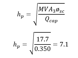
The system has a parallel resonant point of 7.1 which is dangerously close to the dominant 7th harmonic generated in the facility. One solution here will be to lower the capacitor size to move the resonant point. If we choose a 250kVAr bank the new resonant point will be 8.4 which is far enough away from the 7th order. Another solution would be to use a detuned capacitor bank.
Series Resonance in Power System
Series resonance can occur when the series combination of the facility transformer inductance and the shunt capacitor bank in the facility resonates at a harmonic frequency that in injected from the distribution system. In this scenario, the facility itself may not be a significant harmonic current generator but can still experience the harmonic effects of resonance due to the series LC combination ‘sinking’ significant harmonic current from the upstream distribution system. Below is an example of the system that has the potential to go in to series resonance.
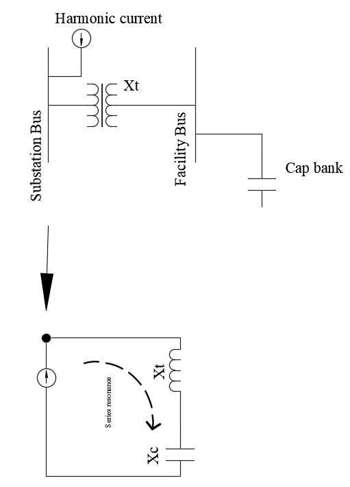
The voltage across capacitor is magnified and distorted and can be given as:
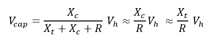
Where Vh is the harmonic voltage present in the system. R is the inherent series resistance of the circuit above and is not shown in the figure. Note that at resonance value of Xt and Xc will be equal and opposite in magnitude hence cancel each other.
Series and Parallel resonance in practical power system application
Practically speaking a series resonant condition will also have a parallel resonance condition due to circuit topology. In the figure below, Xt is the facility transformer reactance and Xc is the facility capacitor bank reactance. Source reactance is given by Xs.
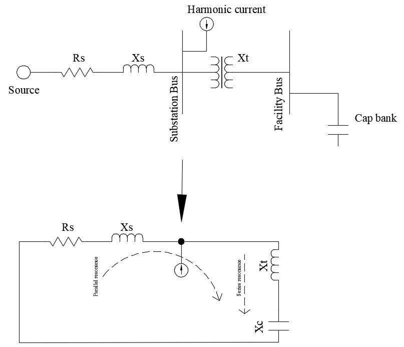
A system as shown will have its first series resonant point determined by Xc and Xt and first parallel resonant point determined by Xc, Xt and Xs.
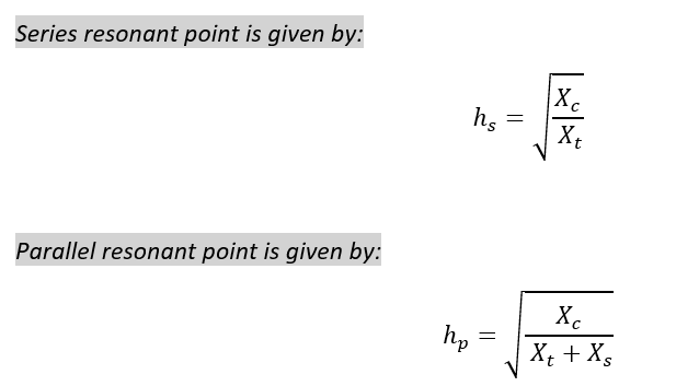
From the equation for series and parallel resonance it can be observed that the parallel resonant point is always lower than the series resonant point in a practical power system installation.
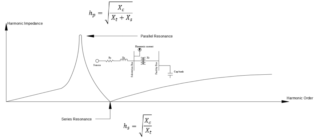
The difference between series and parallel resonance in power system is that series resonance creates a low impedance (draw maximum current in to the system) whereas parallel resonance creates a large impedance which even in the presence of small current can create large harmonic voltage drop and hence cause voltage stress related damages.
Below calculator can be used to find series and parallel resonant frequency for a simple system.
Harmonic Filter Resonance
An important observation can be seen by observing the graph above. Things discussed about series and parallel resonance can also be applied to a shunt harmonic filter. When the filter is sized correctly for the application, the series resonant point will be the harmonic order that needs filtering while the parallel resonant point will be at a point away from any system generated harmonic frequencies. Now assume some of the capacitors in the filter fails. The loss of capacitance (increase of Xc) results in movement of series and parallel resonant point which before failure was located in ‘safe’ spots but may have shifted to more problematic regions after capacitor failures. The resulting filter could draw excessive harmonic current (series resonance) and fail or create high voltage distortion (parallel resonance).
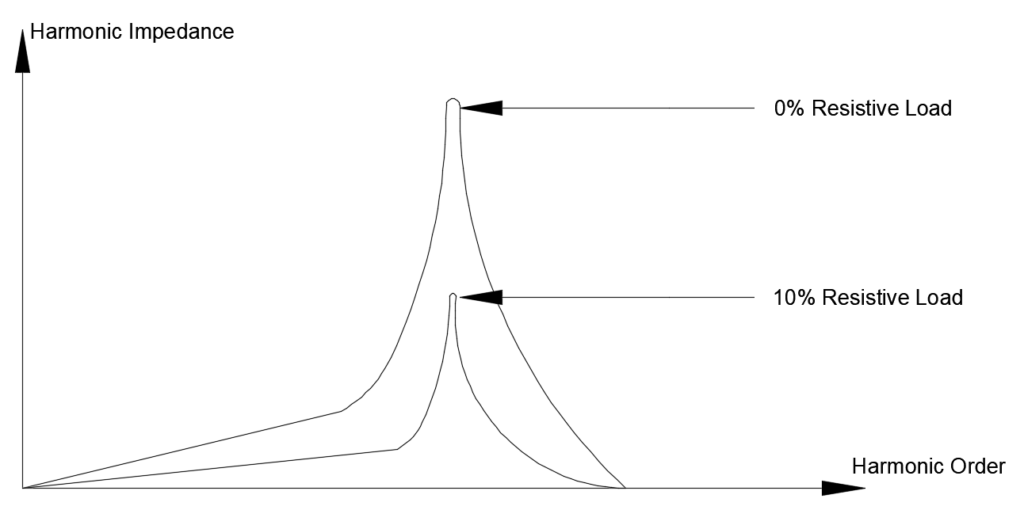
Effect of circuit resistance in mitigating resonance
Damping provided by resistances in the power system is helpful in reducing the catastrophic effects of power system resonance. As little as 10% resistive loading can have significant beneficial impact on peak impedance. Note that circuit resistance does not remove harmonics, it only reduces (dampens) the damaging results caused by resonance. Utility companies are at advantage in this respect as they can physically change the location of harmonic filters, capacitor banks to a location that offers extra series line resistance. Industrial installations do not have this luxury and usually have limited options while installing capacitor banks or filters.
Capacitor banks are typically installed at the low voltage substation bus immediately after a substation transformer. The X/R ratio at such a location tends to be high or in other words the resistance at that location is relatively less and hence parallel resonant peak will be very sharp and high. Application of capacitor banks at such location needs to be reviewed to determine where the resonance point lies (use above calculator as a preliminary check before using engineering simulation software). If the resonant point of the system lies close to one of the dominant harmonics produced in the facility (say 5th, 7th etc.) then we have a problem. The solution will be either to change the size of the bank or use a ‘detuned’ capacitor bank.
Small fractional HP motors slightly helps with damping system resonance as their apparent X/R ratio is low. On the other hand, larger HP motors have high X/R ratio and may do the opposite. Very large motors also tend to affect the system frequency response characteristic and may shift the system resonant point. An engineering analysis will need to include such large (>500HP) motor loads.
Conclusion: Harmonic resonance is a power quality issue that is difficult to visualize as the damages caused due to resonance would have brought the system out of resonance (self-correcting) by the time the engineer is performing measurement or analysis. Hence the important steps in diagnosing harmonic resonance is to first identify if the system configuration can drift in to series or parallel resonance condition as detailed in this article. A detailed computer based harmonic analysis can usually identify the resonance condition.
Other related articles: Power Factor Calculator, Resonance Calculator, Harmonic Filter Calculator, Star and Delta Connection of Capacitors, KVAR to Amps Calculation