Common impedance coupling can cause a variety of issues in communication and control applications. Common impedance coupling occurs when two or more circuits share a common current path. Common current path could be supply circuit, return circuit or both.
Consider an example as shown in figure 1. Two loads share a common ground return path with impedance Zg. PLC load is only 3 Watts whereas the switched load is 3 Kilowatts. Initially switch S/W is open and voltage across PLC is ~120V. When 3KW load is switched ON, voltage across PLC drops to 108.6V. This is due to large current flow through Zg creating a voltage drop Vg. Effective voltage across PLC will be 120- Vg. This phenomenon is known as common impedance coupling or conducted coupling.
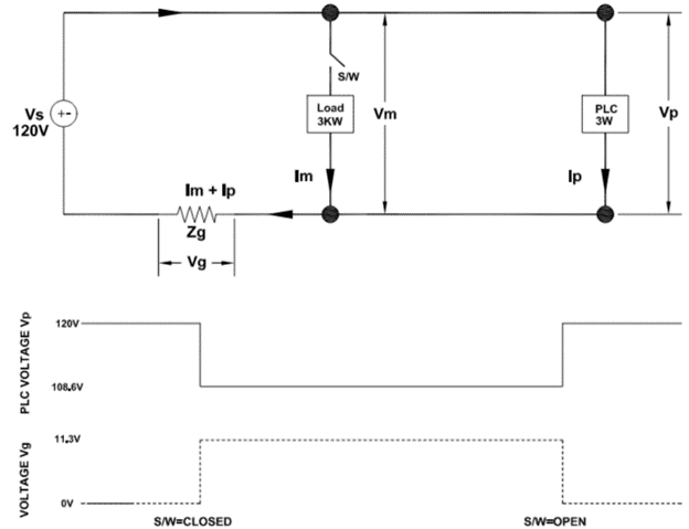
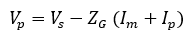
Voltage across PLC load can be written as:
Voltage profile across the smaller PLC load is totally dependent on the frequency of switching and connected load of the larger load. Voltage drop across the smaller ‘victim’ load is influenced and modulated by current flowing through ‘culprit’ load. In figure 1, PLC load is the victim and the 3KW load is the culprit.
A familiar example of common impedance coupling that everyone can relate is lights getting dimmed when a large motor or air conditioning equipment starts.
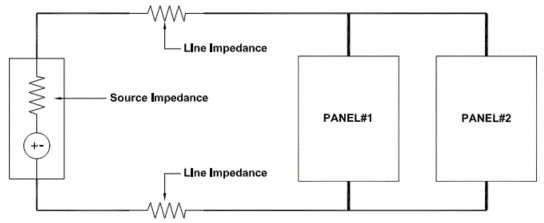
Figure 2 shows a typical power distribution system. Change of load current in panel#2 will affect available voltage at panel#1 due to common line impedance and common source impedance. If panel#1 is connected directly to source, significant improvement in noise coupling can be made. However, there will still be some noise coupling through the common source impedance.
Methods to minimize common impedance coupling are:
- Minimize the shared impedance. For example, at lower frequency use thicker wire with lower resistance and at higher frequencies use wires with low inductance.
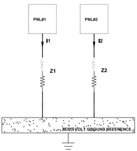
- Rearrange circuits so that shared current path is avoided. Single point grounding avoids common impedance coupling by diverting currents through separate conductors.
- Do not mix circuits with widely different power level when they share a common return path. For example, in figure 1 circuits operate with widely different power requirements (3W & 3KW) which is not recommended.
At power system frequency single point grounding provides effective solution against common impedance coupling. However, it has to be kept in mind that higher frequency ground currents (from VFD switching, SCR controlled devices) will experience higher impedance due to higher ground wire impedance (wire inductance). Multipoint grounding is recommended for higher frequency applications. In addition, at high frequencies, single point ground invariably become multipoint grounded system due to system stray capacitance.
At frequencies below 100KHz single-point grounding may be preferable and above 100KHz multipoint ground system is preferred.