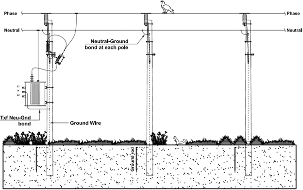
Power system grounds are usually single-point grounded and is most effective at low frequency from DC to about 20 kHz. At frequencies above 100kHz and for utility distribution systems, multipoint grounding has some advantages. Multipoint grounding scheme connects multiple devices to a common ground plane using dedicated ground wire lead. Example of a multipoint grounded utility distribution system is shown in figure 1. In this article multipoint grounding as applicable to utility power distribution system is discussed.
By using multipoint grounding, we can control noise voltage by minimizing the ground circuit impedance. At high frequency this means minimizing ground inductance. In power system applications, multipoint grounding also minimizes the ground resistance.
Ground wire vs Ground strap for high frequency grounding
Multipoint grounded systems are grounded to the nearest available ground plane. Multipoint grounded utility power distribution system has neutral point grounded/earthed at each pole. Advantages of multipoint grounded distribution system is:
- The effective ground resistance of the system will be the resistance of each pole in parallel with every other pole. This results in an overall ground resistance that is much less than a single ground rod.
- Ground wire inductive impedance of each pole will be in parallel with each other. Effective inductive impedance of ground wire will be very low.
- There is no common impedance coupling and voltage drop across each ground lead is a function of its own wire impedance.
- A conductor that is downed at any given pole will have multiple current return paths back to source. This results in faster protective device clearing time. This is very advantageous in utility overhead distribution systems.
High impedance in earth ground wire due to magnetic field
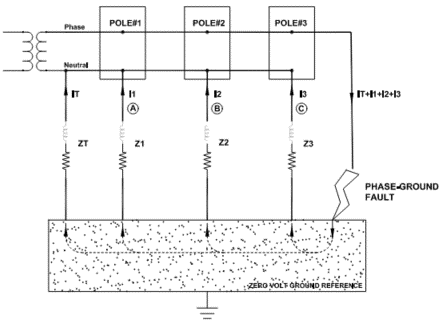
Figure 3 shows utility distribution system with three distribution poles similar to figure 1. Transformer neutral is connected to ground/earth and overhead distribution lines carry the phase and neutral conductors. At each pole the neutral wire is locally grounded thereby making this system a multipoint grounded system When a phase-ground fault occurs after pole#3, fault current can flow through multiple paths in a multipoint grounded system. The impedance of ground wire for each pole is in parallel and net impedance will be lower than any single ground wire. Similarly, the earth resistance (soil-to-ground wire) resistance of each pole will be in parallel with other thereby reducing the net ground resistance. Combination of these factors result in large fault current flow and hence faster protective device clearing.
If there was no multipoint grounding for the system shown in figure 1 and 3, a downed phase conductor will result in a high impedance phase-ground fault. Current flow from the point of phase-ground fault through ‘physical earth’ and back to transformer neutral will be less as this is a high resistance path. Physical earth is not a good conductor of electricity. Fault current will be less, and protective device may take very long to trip or may not trip at all. This is also a safety hazard and many fatal accidents have occurred due to downed phase conductors. Higher ground circuit impedance due to lack of multipoint grounding resulted in high ground circuit impedance and thereby less ground fault current. Protective device did not open as the fault current was well below its set point.