High impedance in earth ground wires can be caused due to commonly known reasons such as loose connection, having a smaller diameter conductor etc. In this article another phenomenon by which earth ground wires can attain higher impedance due to magnetic interaction with ferrous metallic conduit is discussed.
When insulated ground (earth) wires are installed in ferrous metallic enclosures or conduits, the interaction of AC magnetic field with ferrous metallic enclosure can lead to ‘choking’ effect. Current flowing in such a ground wire will experience higher impedance due to the additional inductance arising due to magnetic interaction between wire and metallic conduit. Note that metallic conduit needs to be of ‘ferrous’ material for this phenomenon to occur. Examples of ferrous conduits are rigid metal conduit (RMC), intermediate metal conduit (IMC) and electrical metallic tubing (EMT). Common reasons to install ground wire in a metallic conduit is to prevent damage, theft, aesthetics etc.
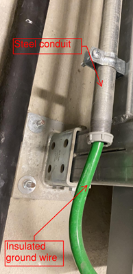
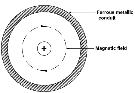
National Electrical Code [NEC] article 250.64 (B) mentions about requirements to protect copper or aluminum copper conductors from physical damage. Metallic steel conduits are commonly used to achieve this protection. Current flowing through insulated ground conductor set up alternating magnetic field which will induce current in the metallic conduit. By Lenz’s law this induced current in conduit will flow in such a direction to oppose the original current (through the ground wire). This is the mechanism by which the ground current experiences higher impedance when installed in ferrous metallic conduit. Note that ground conductors for DC applications do not experience this phenomenon.
During a ground fault, current of hundreds or thousands of amperes will flow through the ground wire. Even a small increase in ground wire impedance can lead to negative effects, including ground current taking alternate paths, longer ground fault clearing time for protective devices etc.
Note: Terms ground and earth wires are used interchangeably in this article.
Normal wire impedance (Z) can be written as:
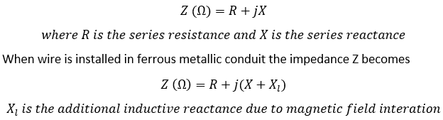
Recommended installation method to avoid additional impedance
When ground (earth) wire has to be installed in a conduit, the following points may be considered.
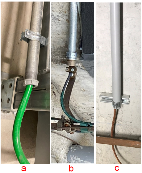
- Ferrous metal conduit needs to be bonded to insulated ground wire at the start and end of the conduit. Even if ground wire is bare copper (non-insulated), it is a good practice to bond the bare wire to both ends of conduit. See figure 3. Bonding jumper size need to be atleast same as the ground wire enclosed within the conduit.
- Non-ferrous metallic conduit such as Aluminum rigid conduit (ARC) offers good physical protection while avoiding the need for extra ground wire bonding. No additional impedance to ground wire is obtained when wire is installed in non-ferrous metallic conduit.
- Non-metallic conduit such as PVC conduit, fiber glass conduits do not have any issue with higher ground wire impedance. However, these conduits may not offer physical damage protection that the metallic conduit offers unless impact and crush resistant PVC is selected.
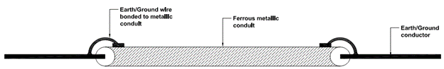
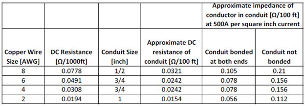
Table 1 lists impedance of four ground conductors with and without conduit bonded at both ends. It is seen that impedance when conduit is NOT bonded at both ends is double compared to when bonded at both ends. Note that it is the impedance that is of importance here and not DC resistance of ground wire.
When a conduit is bonded at both ends with the enclosed ground conductor, the effective circuit is a parallel circuit with conductor and conduit both becoming path of the ground current. Ground current will be shared between the conductor and conduit depending on the relative impedance. Many manufactures produce grounding and bonding fittings that are specifically listed for this purpose.
At 50/60Hz, current will divide equally between conduit and ground conductor. Higher frequency harmonic current will have a tendency to flow mostly in the conduit due to skin effect.
Reference 1: Soares book on grounding and bonding, IAEI