Power cables used for transmission and distribution of power have distributed capacitance. Medium and high voltage power cable consists of center conductor and an outer metallic shield separated by insulation which has the characteristic of a capacitor (two conductors separated by insulation). When AC voltage is applied, this distributed cable capacitance will draw capacitive current from phase conductor to shield (ground). Depending on the type of cable, voltage and length of circuit capacitive current can be tens to hundreds of amperes. Cable capacitive current is also known as cable charging current. This phenomenon also occurs in overhead transmission lines and is known as line charging current.
Though charging current can occur at any voltage level, its effects on power system performance is of significance when cables are applied at medium or high voltage. Low voltage cable charging current is not of particular interest except when calculating high resistance grounding systems.
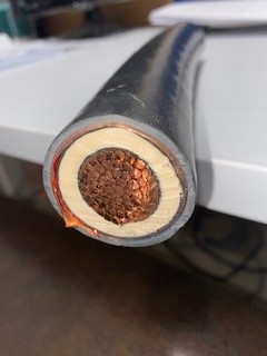
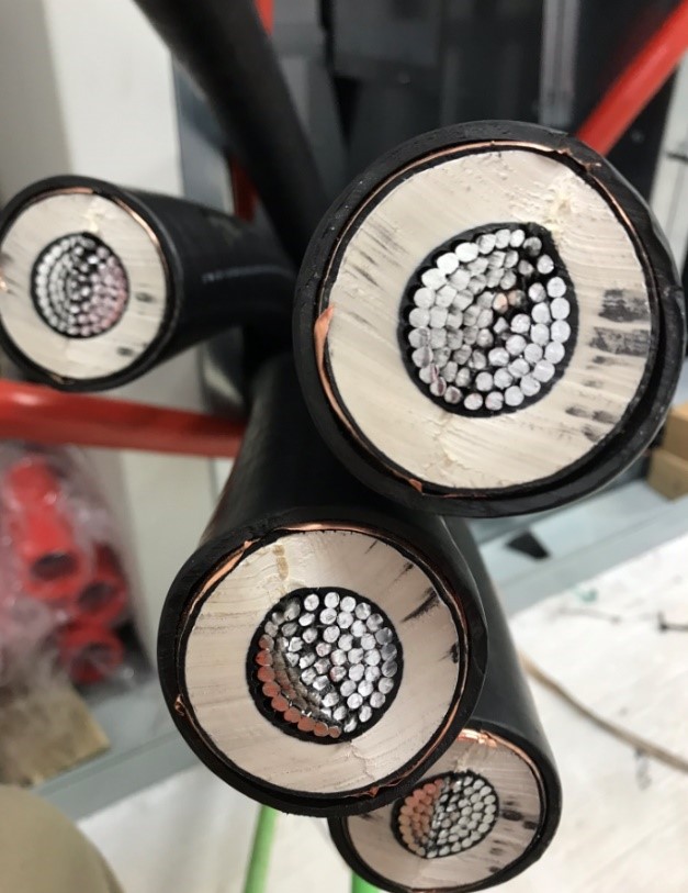
Figure 1 shows cross section of a cable with conductor, shield and insulating medium. Cable conductor to shield capacitance is distributed throughout the length of the cable. Cable manufactures usually specify capacitance per kilometer or per thousand feet. Even though there are many cable manufactures, the range of capacitance for a given voltage, conductor diameter and type of insulation usually falls in a typical range. This allows for estimating the capacitance and hence the charging current even if data sheet is not available. See capacitive charging current calculator in this article.
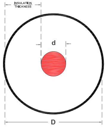
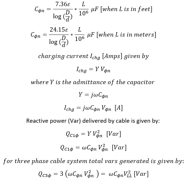
Consider a cable shown in figure 2 with conductor diameter of ‘d’ and diameter over insulation of ‘D’. Let the length of cable be ‘L’ and dielectric constant of the insulation be ‘ϵ’. Line to neutral capacitance for length ‘L’ can be calculated as follows.
Overhead transmission line also exhibits charging current phenomenon due to phase-phase and phase-ground capacitance. Cable fed systems produce much higher charging current since the spacing between conductor and ground (shield) is much smaller and the permittivity (ϵ) of cable insulating medium (XLPE, EPR) is 2-4 times that of free air. Reference [1] shows an example in which a 345kV, 5 mile cable produces as much charging current as a 100 mile overhead line of similar voltage meaning the capacitance to ground for cable is much higher than overhead lines for a given circuit length.
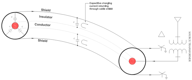
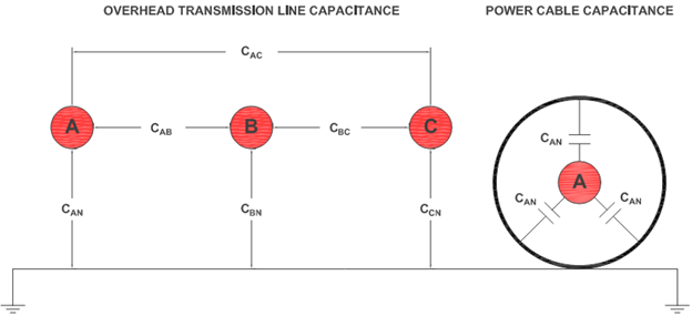
Figure 3 shows major capacitances for overhead line and capacitance for shielded power cable. Overhead transmission line capacitance is not discussed in this article.
Factors on which cable charging current depends are:
- Capacitance per unit length
- System frequency
- Phase-neutral voltage
- Circuit length
The capacitive nature of cable also leads to generation of capacitive ‘vars’ that will flow back into source. For small lengths or for cables operating at lower end of voltage (<100kV) this may not be an issue. However, for long cables or cables operating at high voltages the reactive power generated could become large (hundreds of kVar). When cable is connected to a larger system the vars will be used elsewhere. However, if the circuit is long and open circuited or lightly loaded, then generated vars has nowhere to go and can lead to Ferranti effect in cables.
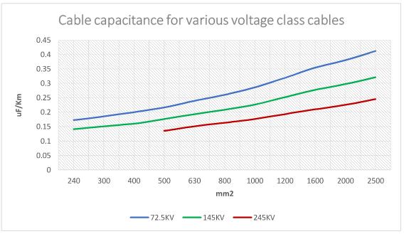
Figure 4 shows the variation of cable capacitance with conductor diameter for three different voltage class cables. Following can be inferred from this graph:
- For a given voltage class, capacitance increases as the conductor diameter increases.
- Increase in capacitance with conductor diameter is mostly linear.
- For a given size, higher voltage class cable has lower capacitance per unit length when compared to a lower voltage class cable. This is expected since higher voltage cables will have larger distance between conductor and shield (thicker insulation). Thicker the insulation, smaller the capacitance.
Calculator below can be used to obtain approximate values of cable capacitance, charging current and generated capacitive kVar for a given length.
Percentage insulation in MV Cables
Negative effects of cable charging current
- Charging current can cause nuisance tripping of line differential relays since charging current is an unbalanced current entering the 87L zone.
- Performance of differential and directional relays that use negative or zero sequence components are at risk during line energization, unequal pole closing or under pole-open conditions with low load.
- Certain power systems transients can cause larger charging current to appear when compared to steady state. Relays that are set based on steady state considerations may misoperate. Few examples of transients that may affect charging current magnitude are:
- Line energization
- External fault
- Single pole opening
- Excess capacitive vars produced on a line that is open circuited or lightly loaded can lead to voltage rise due to Ferranti effect. On the positive side, when line is loaded, capacitive vars can help with system power factor and also help improving voltage drop.
- Charging current reduces the amount of current and hence power that can be delivered to the load. It is possible for a very long cable to carry 100% capacitive charging current making the cable unable to supply any useful load. Length of cable at which capacitive charging current equals rated current carrying capacity of line is known as cut off length and no useful power can be transmitted in such case.
Transformer differential protection
Mitigating effects of charging current
Charging current arises due to physical property of cable and its negative effects can only be compensated but not eliminated.
- Apply line reactors to inject inductive vars which will cancel capacitive vars.
- De-sensitize relay settings to account for charging current.
How to measure Reactive power?
Surge impedance loading of transmission line
References
[1]: Charging Current in Long Lines and High-Voltage Cables – Protection Application Considerations, Yiyan Xue, AEP; Dale Finney and Bin Le, Schweitzer Engineering Laboratories, Inc.