Surge impedance loading [SIL] of a transmission system is the power delivered by a lossless line to a purely resistive load, the value of which is equal to surge impedance. Surge impedance can be obtained by using the equation below where L is the inductance per unit length and C is the capacitance per unit length. Unit of surge impedance is Ohms.

Surge impedance is independent of line length. A lossless line operating at its nominal voltage terminated in its surge impedance Z0 is said to be Surge Impedance Loaded [SIL].
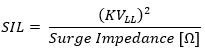
Surge impedance loading in MW is given by line-line voltage (in KV) divided by surge impedance of the transmission line:
Surge impedance load of a transmission line can also be defined as the unity power factor load that can be delivered over a lossless (R=0) line such that I2XL = capacitive charging KVAR of line. When line is SIL loaded sending end and receiving end voltages will be equal in magnitude but different in phase position. Real power flow on a lossless line terminated at SIL remains constant from sending end to receiving end while the reactive power flow is zero.
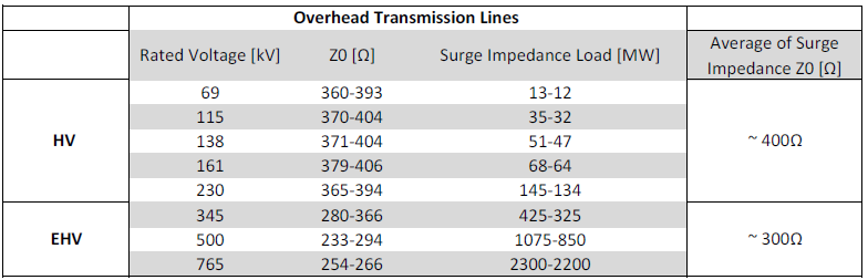
Surge impedance for transmission lines may vary from 200-400Ω depending on the voltage class and its phase angle may vary from 0-15degree. Table below lists typical values of HV and EHV overhead line surge impedance values.
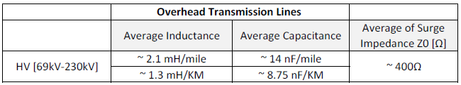
For overhead lines the following rule of thumb may be used for calculating the series inductance and shunt capacitance.
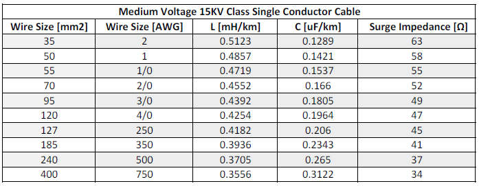
For cable systems the surge impedance is usually lower at around 1/10th of that of overhead lines. Table below shows the surge impedance a particular manufacturer 15kV single conductor power cable.
Surge Impedance
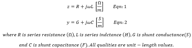
Transmission line constants [R, L, C] etc. are per-length values which are uniformly distributed along the length of line. For a unit length of line, series impedance and shunt admittance can be written as:
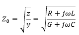
Characteristic impedance Z0 of this line is defined as:
For a lossless line R=G=0 and characteristic impedance and propagation constant can written as:
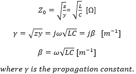
Characteristic impedance Z0 for a lossless line is called as Surge Impedance.
Voltage Profile of Surge Impedance Loaded Line
Transmission lines are not usually terminated in its characteristic [surge] impedance. Load type determines the impedance presented to the line. However, we can consider some extreme cases to evaluate. These are lossless transmission lines terminated in:
- Infinite Impedance [No Load]
- Surge Impedance
- Zero Impedance [Short Circuit]
In each case the voltage at the end of the line will be different.
- When lossless line is terminated in infinite impedance [No Load], voltage at remote end is given by:
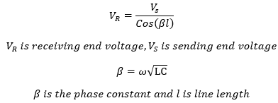
2. When lossless line is terminated in its surge impedance, voltage at remote end is given by:

Voltage at the receiving end is the same as the voltage at sending end.
3. When lossless line is terminated in zero impedance [short circuit], voltage at remote end is zero.

Cases 1 through 3 can be plotted as shown in figure 4.
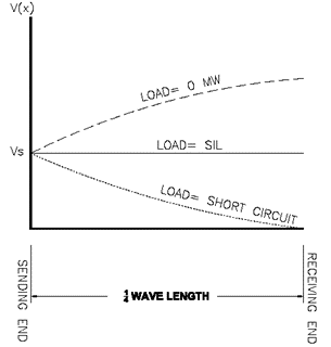
It can be seen that an un-loaded and long transmission lines can have higher voltage at the receiving end compared to sending end. In practice, transmission line voltages decrease when heavily loaded and increase when lightly loaded. This effect is known as Ferranti effect. Ferranti effect can lead to damaging over voltage at remote ends of un-loaded lines. Shunt reactors are installed at remote ends to mitigate this effect.
Line that is surge impedance loaded will have flat voltage profile while the line that is short circuited will have zero voltage at the line end.
Real world fully loaded line with lagging power factor will have voltage profile that lies above the short circuit and below SIL loaded lines.
Surge Impedance and Line Loading
Though we can define a term called as Surge Impedance Load [MW] for a lossless transmission line, the term is not a measure of maximum power that can be delivered over that line. Maximum power that can be transmitted is determined by:
- Thermal limit of line
- Voltage drop limit
- Steady-State stability limit
Read: Voltage drop and power factor
Short Lines (<80km): Conductor maximum design temperature determines the thermal limit of the line. Loadability of short lines (<80km, for 60Hz lines) is determined by conductor or connected equipment thermal limits.
Medium Lines (<300km): For medium long lines (<300km) line-loadability is determined by voltage-drop limit.
Long Lines (>300km): For long lines over 300km steady-state stability limits determines the loadability. Stability refers to the ability of synchronous machines on either end of a line to remain in synchronism.
Practical use of surge impedance is mostly academic and is used for certain types of power system analysis.