Power system grounds are usually single-point grounded and is most effective at low frequency from DC to about 20 kHz. There are two ways by which power circuits are single point grounded: Series Connection and Parallel Connection.
By using single-point grounding, we can control the amount of ground current Ig that flows through ground wire and hence control the voltage drop.
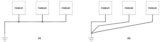
Series Connection
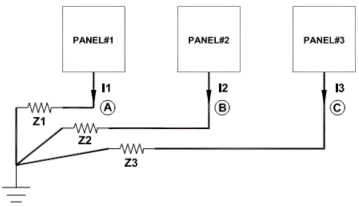
Schematic of series connected single-point connection is shown in figure 2.
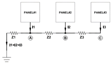
Potential at point A and C is given by:
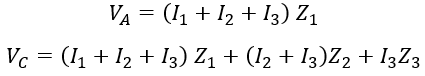
Series connected single-point grounding is the most undesirable single-point ground system but due to its simplicity is used in most power distribution systems. In figure 2, ground potential at point C is highest while the potential at A is lowest. Devices that are most sensitive to ground potential should be connected at point A.
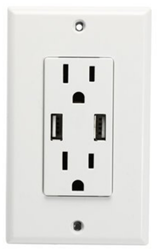
Examples of series connection are 120V receptacles. These circuits originate in a distribution panel and is daisy chained through multiple receptacles. Ground wire for these receptacles will be in series connection as shown in figure 2.
Parallel Connection
Parallel connected single-point grounding is a more desirable single point grounding scheme but can be very cumbersome to install as each panel need separate ground wire to the zero-voltage ground reference.
Parallel connection can be used for dedicated circuits like motor circuit, control panel, panels containing sensitive electronics etc.
Cross coupling of ground voltage between various circuit can be avoided in this method. Ground potential of each circuit now is a function of its own ground current and impedance.
Practical single-point grounded systems are a combination of series and parallel connection and is a compromise between need to meet noise requirements and avoiding more complex wiring needs. It is recommended to avoid mixing circuits with varying power requirements in one ground return circuit. For example, several low power circuits could be connected in series and high-power circuits could be connected in parallel.
Ground wire vs Ground strap for high frequency grounding
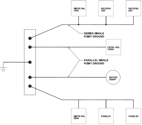
Common power system distribution circuits have ground wire originating at service entrance panel series connected across multiple branch circuits. There will be many such circuits originating from service panel which will all be parallel connected to service entrance ground. Example of a typical single-point grounded system is shown in figure 5.
Draw back of Single-point grounded system
At high frequencies single-point ground is undesirable as inductance of ground wire increases the ground impedance. At even higher frequencies, ground circuit impedance can be very high and can radiate (act as antenna) if the length of wire with odd multiples of quarter wavelength. To maintain low impedance and to minimize radiation ground leads should always be kept shorter than 1/20th of wavelength [Ref 1].
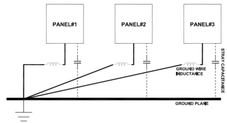
At high frequency the impedance of the ground wire becomes very high while at the same time the impedance of stray capacitance becomes lower. Ground current hence will flow through the stray capacitance instead of through ground wire. The system now looks like a multi-grounded system instead of single-point grounded system as shown in figure 6.
Summary
Single-point grounding is the most common method of power system grounding. Neutral point of service transformer will be grounded at the utility service incomer. Branch circuits then carry this ground to all panels and sub distribution panels. Single-point ground can be sub divided into series and parallel type. Series type is most common of the two as it involves less wiring and is less cumbersome to install. However, series single-point grounding has the draw back that noise voltage could cross couple due to common impedance coupling. Parallel type single-point connection does not experience cross coupling but involves more wiring and is more cumbersome to install.
High Impedance in earth ground wire due to magnetic field
Ref 1: Electromagnetic Compatibility Engineering, Henry W Ott, Wiley.