Modern high and medium voltage cables [HV and MV] are precisely engineered components key to safe and efficient distribution of electrical energy. Cable insulation at HV and MV experience large electrical stress as the distance between conductor and the grounded shield is very less compared to overhead lines. Readers are encouraged to review this article about Medium voltage cable construction. High voltage cable is engineered to minimize electrical stress [Volts/meter] on insulation. Cable shields are provided to achieve symmetrical and uniform electric field [E-Field] distribution around center conductor thereby minimizing electrical field stress. National Electrical Code [NEC] standard 310.6 only allow non-shielded cables for voltage less than 2,000V and with some listed exceptions can be used up to 2,400V. Application above 2,400V shielded cables are required meaning cable terminations are required for all cables applied at voltages above 2,000V or 2,400V. In this article the terms HV and MV are used interchangeably and refers to cables that are shielded in some fashion.
Read: Cable shield grounding
A shielded cable has uniform electric field density along the axis, but the field itself varies in the radial direction. When HV cable need to be connected to an equipment, the grounded shield needs to be stripped back which then distorts the symmetrical E-field distribution. Electric field tends to concentrate at the edge of shield discontinuity and will eventually overstress and damage the cable insulation. Cable terminations help manage the electric field stress on insulation and hence prevent premature cable damage. Expect for unshielded MV cables, all MV and HV cables require some sort of cable termination.
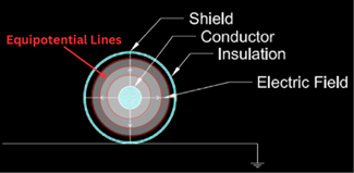
Equipotential Lines: With reference to HV cable terminations, equipotential line is a commonly used term. Similar to contour lines on a map that traces lines of equal altitude, equipotential lines connect locations that are at same electric potential. Conventionally, electric field originate on positive charge and terminate on negative charge. In the case of cable, E-field originates at the center conductor and terminate on the grounded shield. See figure 2. Equipotential lines can easily be drawn once we know the E-field pattern as the equipotential lines are always perpendicular to the electric field.
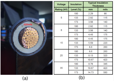
When HV or MV cable needs to be terminated, shield need to be removed for a distance to expose the center conductor. If the shield is not sufficiently stripped back, the small distance between conductor and shield (Example, 220mils for 15kv class cable) is not sufficient to prevent flashover or surface tracking. Table below shows the distance between conductor and shield for medium voltage cables from 5kV to 35kV.
Read: Percentage insulation of medium voltage cables
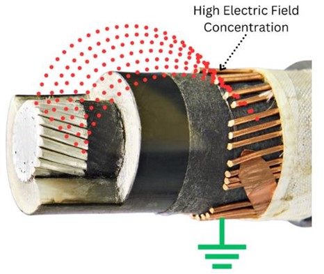
Due to the reasons given above, shield needs to be removed for a set distance (depends on voltage class). While this alleviates any flashover concerns, E-field distribution around the conductor axis is distorted now. E -field is no longer symmetrical around the cable axis and now congregates around the edge of the grounded shield as shown in figure 4. Note the high electric field stress near the cable shield discontinuity which will eventually cause localized insulation overstress that can lead to cable damage.
Read: Charging current in high voltage cable
To prevent cable insulation overstress and damage, steps need to be taken to control E-field when terminating MV and HV cables. This is known as electrical stress control and is the reason behind need for specialized terminations when applying MV and HV cables. There are two common methods for stress control:
- Geometric stress control
- Capacitive stress control
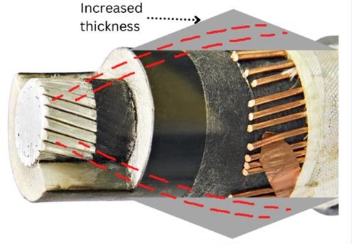
Geometric stress control: Geometric stress control method increases the effective thickness of the insulating material near shield discontinuity. This is the method that is used from early days of cable terminations. The cone shaped component forces the electric field stress to be spread out more evenly thus reducing stress at the discontinuity. Disadvantage of geometric stress control is the thicker profile, limited bend flexibility and difficulty of installation. See figure 5.
Capacitive Stress Control: This method is also known as High-K stress control. In this method a termination material is added on to the area where shield is removed. This material has very high dielectric constant (K) compared to say or air or even XLPE/EPR insulation. Application of this material causes the E-field to refractively flow through the material with high K rather than through cable insulation. E-field stress is reduced from hundreds of volts/mil to values found in cable (~50V/mil). Advantage of capacitive stress control is thinner profile of final termination, bend flexibility and ease of installation. See figure 6.
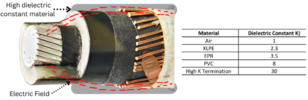
Capacitive stress control could be heat shrink, cold shrink or hand wrapped.

When the symmetrical construction of cable is disturbed, equipotential lines will no longer be symmetrical around conductor axis. Equipotential lines for an unterminated cable with shield removed [Figure 7(a)] shows close spacing in the area around the shield discontinuity indicating high electrical stress. The main purpose of cable termination is to re-direct this stress from the shield discontinuity. Figure 7 (b) and 7 (c) shows equipotential lines for geometric and capacitive type cable termination. Note the increased space between the equipotential lines in the area around shield discontinuity indicating reduced electric field stress in that region.
Read: Positive and zero sequence impedance of cable
Standards for Cable Termination
Terminations are not addressed by UL or NEC. IEEE48 and IEEE386 addresses cable terminations. Various classes of termination per IEEE Standard 48 are Class I, Class II and Class III.
Class I: Characteristics of class I terminations are:
- Provides electric stress control for cable insulation
- External leakage insulation between conductor and ground
- External environment sealing
Class II: Characteristics of class II terminations are:
- Provides electric stress control for cable insulation
- External leakage insulation between conductor and ground
Class III: Characteristics of class III terminations are:
- Provides electric stress control for cable insulation
Class I terminations are recommended if there is presence of contaminants, moister or in general a more secure installation is desired.
Read: Surge impedance loading
Insulation skirts in High Voltage Cable termination
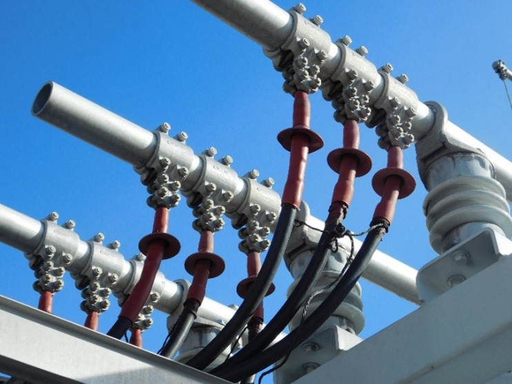
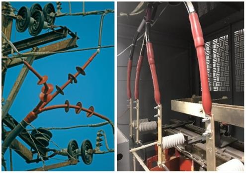
You must have seen cable terminations (especially outdoor terminations) that has unique skirts to it. See figure 1, 8 for an example. What is the purpose of having insulation skirts?
Apart from electric stress control that is discussed in this article, the function of cable termination is also to provide protection from flashover damage and tracking damage. Flashover concern is addressed by selecting the termination based on the Basic Impulse Level [BIL] desired.
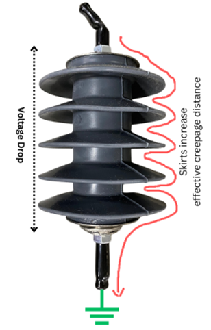
Insulation skirts are used in cable terminations, substation insulators, lightning arrestors to increase the effective ‘creepage’ distance between the conductor and the grounded structure. Cable terminations used outdoors or in high contamination environment are subjected to accumulation of dirt, dust, salt etc. that can cause leakage current to develop between conductor and ground/shield, the magnitude of which depends on the resistance of insulation surface. Cable termination need to be made of track resistant materials however this alone may not be sufficient to increase the tracking resistance and prevent tracking damage. Insulation skirts are used to create breaks in the contamination path and to increase tracking resistance. Having insulation skirts reduces the probability of tracking damage.
Use of skirts also helps in keeping the cable termination compact since the creepage distance is increased by use of skirts avoiding the need for longer termination.
References: [1]: 3M, Power cable splicing and terminating guide