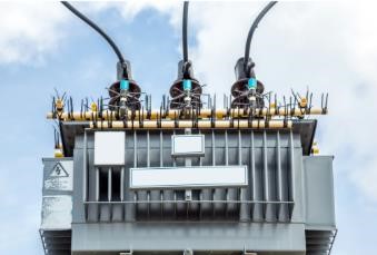
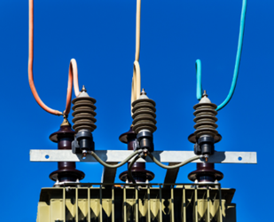
Grounding transformers are used in utility and industrial distribution systems to ‘create a grounded system’ from an otherwise ungrounded source. Typical example of this is an existing delta or wye ungrounded secondary service and the user wants to convert to a grounded system without changing source transformer grounding.

A solution to convert to grounded system is to install grounding transformer. Renewable sources like wind, solar etc. can also make use of grounding transformers to create an effectively grounded system. Grounding transformers can be of wye-grounded delta or zig-zag type. Grounded wye transformers have primary winding connected in wye-ground (star-ground) and secondary side in delta. Zig-Zag is the most common type of grounding transformer and may be less expensive and smaller than wye-delta while providing similar benefits.
In this article only wye-delta grounding transformer is discussed. In general grounding transformers are used to:
- Stabilize system neutral at ground potential
- Provide path for ground fault current
- Limit transient overvoltage condition
- Permit connection of phase-neutral load

Typically, grounding transformers are used to create a grounded system and not necessarily serve single phase loads (though it is possible). When single phase loads have to be served, transformer kVA and thus cost will increase. When there are no single-phase loads, rating of the transformer can be greatly reduced as the transformer only has to carry normal unbalance current and short duration ground fault current for 10-60 seconds. Magnitude of ground fault current can be controlled by specifying the required zero sequence impedance of the transformer.

Delta secondary side of grounding transformer provides compensating ampere turns [AT] to the flow of primary ground fault current. Closed delta winding is the reason grounding transformer offers low impedance to ground fault current.
Read: Transformer impedance: Why is impedance in percentage?
Grounding transformers can also be used where excessive neutral current is causing stray voltage rise or telephone interference issues. When grounding transformers are introduced at these locations, neutral current is ‘redirected’ back through phase conductors as shown in figure 3.

Neutral grounding resistor [NGR] may be inserted into the neutral circuit to limit fault current to a low enough value that will permit tripping while eliminating damage to connected devices from high magnitude ground faults.
Read: Neutral current transformer
Accidental or protection trip of grounding transformers need to be considered in the design. Disconnection of grounding transformer due to an internal fault will leave the system ungrounded and may go unnoticed unless suitable alarm and signaling is installed.
Read: Single point grounding in power systems
Power rating of grounding transformer
Power rating of a wye-delta grounding transformer can be calculated considering the fact that each leg carries one-third of the fault current.

IEEE C57.32 provides required continuous and short-time ratings for grounding devices. Expected steady state neutral current (either due to normal voltage unbalance or single-phase load) need to be factored into power calculation. If the transformer is solely used for grounding and does not supply auxiliary load, steady state neutral current is the primary determining factor in kVA calculation provided fault current is interrupted quickly. If steady state neutral current is not known, a common thumb rule is to size the unit based on neutral current of at least 3-7% of fault current. If fault current only flows for few seconds, designers can factor short term winding heating into the design leaving neutral current as the deciding factor in kVA rating. Steady state neutral current need to be based on:
- Connected phase-neutral load
- Cable capacitive charging current
- Capacitive leakage current from surge arrestors
- Ground return current from harmonic filters on VFDs etc.
- Any other source of ground return current

Fault current rating is typically short duration from 10-60s. It is expected that the protective device will clear the fault within this duration to avoid overheating the transformer. If fault current is high and can persist for long duration, then fault current becomes the determining factor in kVA rating. If there are neutral resistors, fault may be permitted for a longer duration and transformer size can be reduced. Thermal rating of the resistor now becomes the limiting factor.
Read: How does power transformer saturate?
Delta side of the grounding transformer is ‘buried’ in the transformer and not brought out unless specified. For testing purposes one leg of delta may be requested to be brought out. The Delta side may be used to provide auxiliary power if desired.
Read: Earth resistance calculator for a single electrode
Zero sequence impedance of grounding transformer
Important parameter in the specification of a grounding transformer is zero sequence impedance. Ground current drawn by the unit is given by:

where I0 is the zero-sequence current, V0 is zero sequence voltage Z0 is the zero-sequence impedance. Neutral ground fault current IN is given by:

Normal voltage unbalance will result in the appearance of negative sequence and zero sequence voltage. Zero sequence voltage will drive current through grounding transformer per the equation above. Severe ground current will flow for single phase loss such as an open phase and most severe current will flow for phase to ground fault or double line to ground fault.
Important parameters for specifying grounding transformer
Parameters for specifying wye-delta grounding transformers are given below. Note that many parameters are interlinked. For example, zero sequence impedance determines fault current and hence kVA. An engineering study is required to specify a grounding transformer.
- Steady state neutral current
- kVA of transformer
- Expected fault current
- Fault current duration
- Zero sequence impedance
- Secondary winding buried or brought out
- Auxiliary power from secondary winding if needed
- Basic insulation level [BIL]
- Copper or Aluminum
