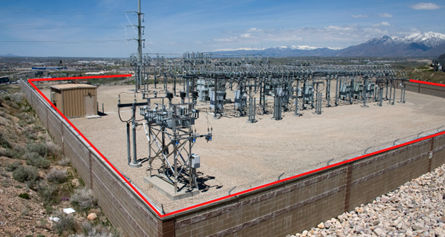
Constructing substation ground grid is the principal method of achieving low substation to remote ground or earth resistance. Ground grid is often comprised of a network of interconnected ground wire or ground strip connected in a rectangular or square fashion which helps in creating an equipotential platform. To further improve ground resistance, number of vertical ground rods are also added to the grid. Entire ground grid is buried at some distance below the surface (typically 0.5m) and backfilled with a layer of crushed rock of high resistivity. This is the typical construction practice of a substation ground grid.

Read: Ground wire vs Ground strap for high frequency grounding
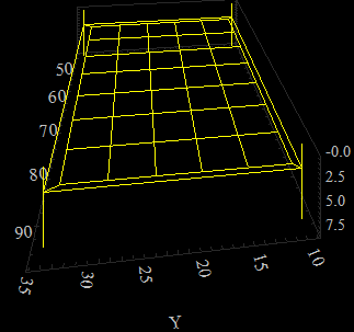
Figure 2 shows example of a grid with horizontal conductors laid out in a square or rectangular formation. At the four corners there are four ground rods driven in to earth.
Read: Stray Voltage-How does it originate?

Ground resistance of substation grid to a remote location on earth, which is assumed to be at zero volts is not easy to measure once construction is completed. To measure grid resistance using traditional method such as fall of potential requires that measurement be carried outside the ‘sphere of influence’ of grid. For many large substations, extremely long measurement traverses are required to get outside the sphere of influence and most of the time will be impractical.
Read: Ghost voltage
This article discusses an equation that can be used to estimate substation ground grid resistance to remote earth when grid area, soil resistivity and total length of buried ground rods is known. Soil resistivity is assumed to be uniform. Value of substation ground resistance to remote earth is given by [Ref 1]:


From the equation above, it can be seen that for earth resistance (Rg) of grid to be low, following parameters play role.
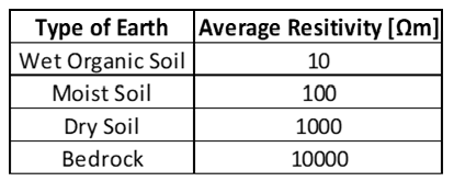
Soil Resistivity [ρ]: Low soil resistivity yields reduced earth resistance. Relationship between soil resistivity and earth resistance is linear.
Surface Area [A]: Grids that occupy large surface area yields lower resistance. There is an inverse relationship between grid resistance and substation ground grid area.
Buried Length [LT]: Lower grid resistance can be achieved by having longer length of buried conductors. Buried conductor length include conductors that are part of horizontal grid as well as total length of vertically driven ground rods.
Read: Single point grounding in power system
Another equation considering buried depth of grid [Ref 2] is given below.

Low effective substation grid resistance is very important in minimizing step and touch potentials in the substation during a fault condition. Low grid resistance has a direct impact on reducing ground potential rise [GPR].
Read: Multi point grounding in power system
Reference 1: IEEE Standard 80-2013
Reference 2: J. G. Sverak, “Sizing of Ground Conductors Against Fusing,” in IEEE Transactions on Power Apparatus and Systems
