Different means of achieving low earth or ground resistance are to drive ground rods, bury wire, copper strip, metallic plate etc. In this article, formula for single rectangular strip electrode buried parallel to surface is discussed. Buried strip electrodes which can also be called trench electrodes makes good contact with earth similar to buried wire electrode.

For a single buried strip, equation for effective earth or ground resistance [Rg] value is given by the following equation [Ref 1]:


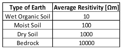
The following calculator can be used to calculate earth or ground resistance for a single horizontally buried strip electrode in ground. Typical resistivity values as provided in IEEE Std 80 can be used or user can input soil resistivity data directly in to calculator. Since the conduction in soil is largely electrolytic, the amount of moisture and dissolved salts affects the resistivity of soil. Without actual measurement, accurate characterization of a particular soil as ‘wet organic soil’ or ‘moist soil’ is hard to define.
Read: Ground wire vs Ground strap for high frequency grounding

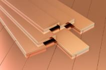
Picture on the left shows a bare copper strip connected to a steel post carrying overhead power lines. Buried copper strip is part of substation ground grid system and the connection to steel post is for equipotential bonding.
Read: Multipoint grounding in power systems
Buried wire or strip electrodes are integral part of substation ground grid layout. Substation ground grid or ground mesh consists of many such buried electrode conductors that are joined together by irreversible connections such as cad weld. In a large substation there may be many locations at which fault current may be injected making ground grid (mesh) the perfect choice. Ground grids are often supplemented by having ground rods at periodic intervals for even better performance.
Read: Single point grounding in power systems

From the equation above, it can be seen that for earth resistance (Rg) of strip electrode to be low, following parameters play role.
Soil Resistivity [ρ]: Low soil resistivity yields reduced earth resistance. Relationship between soil resistivity and electrode resistance is linear.
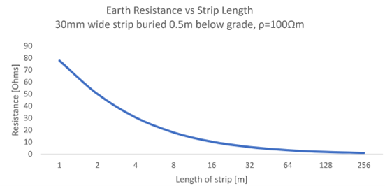
Length of Electrode [L]: Doubling electrode length will reduce earth resistance roughly by ~ 40%. However, extremely long conductors are not recommended due to poor transient performance. Instead, ‘crows foot’ (star) arrangement or a buried grid (mesh) provides better performance.
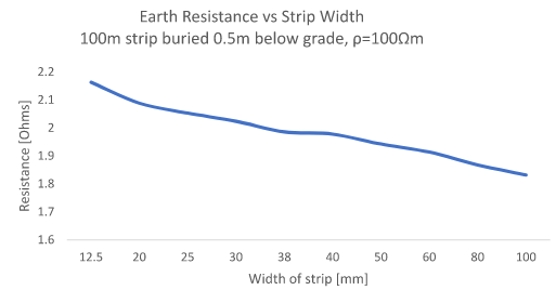
Width of Electrode [2w]: Increasing width of strip only has small influence on reducing earth resistance.
Read: Isolated ground receptacle

Ground grid using buried conductors help to stabilize ground potential rise during fault condition. Buried ground grid conductors are often covered with a layer of crushed stones to increase surface resistance and improve touch and step potential performance.

Often buried strip electrodes are arranged in some pattern such as star formation (crow’s foot) for improved surge impedance performance and to achieve overall lower earth resistance when compared to a single long strip.
Read: Stray voltage- How does it originate?
Comparing round conductor (wire) to flat copper strip it is seen that for same total surface area and circuit length, calculated earth resistance for both is comparable with the flat strip offering 1-2% lower value.
Reference [1]: Power system grounding and transients; A.P. Sakis Meliopoulos
