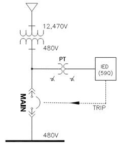
Negative sequence overvoltage protection [ANSI 59Q] is used for detecting phase voltage unbalance or reverse phase condition. Variation of individual phase voltage relative to another, reversal of phase sequence (Example ACB rotation instead of ABC or CW rotation instead of CCW) or phase angle variation will result in appearance of negative sequence voltage.
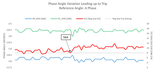
In this article, a real incident of negative sequence trip due to utility voltage phase angle variation is discussed. After retrieving event log from protection relay, it was determined that phase voltage magnitude was within acceptable limits. Typically phase voltage unbalance is the common cause behind appearance of negative sequence voltage. On further investigation it was noticed that B phase voltage showed higher-than-normal angle variation. Instead of being at -120 degrees, the angle was hovering around -117.93 degree. Figure 2 shows the absolute value of phase angles leading up to circuit breaker trip.
Read: Neutral current transformer applied with electronic trip units
Utility supply is expected to have ideal or close to ideal phase angles. These can be 0, -120, +120 degree for sources with ABC and ACB rotation. There could be minor variation of +/- 0.2 degree in any system and is usually acceptable.
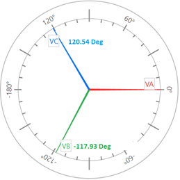
B phase voltage phase angle was found to be -117.93 degrees at the time of trip. Phase-neutral voltages were 285V, 286V, 286V for a 277V nominal system at the time of trip. Calculation of negative sequence voltage [3V2] using the above voltage and phase angles yield 8.4V. Since 3V2 is above the trip threshold of 8 volts, it was concluded that utility voltage phase angle drift led to the trip event. If phase angles were ideal, the measured phase voltage would only have resulted in 0.99V of negative sequence voltage [3V2] and would never have nuisance tripped.
Read: Current unbalance: Causes, Effects and Protection
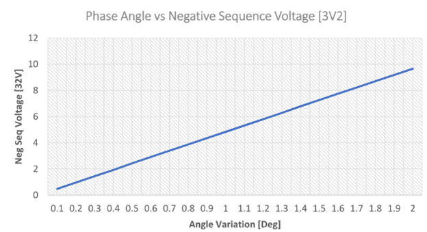
Figure 4 shows calculated negative sequence voltage as the B phase angle is varied for a 277V system. A and C phase angle and voltage are set to nominal value for generating this curve. Graph shows that if the angle drifts to 2 degrees beyond nominal, then negative sequence voltage [3V2] of around ~9.5V can be generated. If there is any voltage unbalance in addition to phase angle drift, negative sequence voltage will be even higher.
Since this is a utility fed source, it has to be assumed that source is producing ideal or very close to ideal phase angle. Measured phase angle could differ due to instrumentation error or characteristics of distribution system. In any case first suspects should be:
- Voltage Transformer (VT) measurement error/defect
- Severe unbalanced line loading
Phase angle shift can also occur for following reasons:
- Phase angle regulator malfunction
- Use of triplex transformers with dissimilar characteristics
- Unequal line impedance or lack of line transposition
First suspect for phase angle variation should be the voltage measuring device (VT or PT). Voltage transformer introduces two types of errors that can affect accuracy of VT measurements: Ratio error and Phase angle error. For this specific incident, no issue with VT accuracy was identified.
Read: Circuit breaker trip due to control circuit ground fault
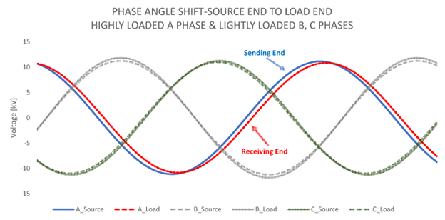
Unbalanced line loading on one or more phases can cause voltage phase angles to drift from ideal. Simulated graph in figure 5 shows source and load end waveform for a three phase 12.47kV line. Phase ‘A’ is 100 times more loaded than ‘B’ and ‘C’ phases. Notice that A phase load end voltage angle has drifted away from the source end angle. At the load end, phase angle drift from ideal causes negative sequence voltage to appear. Refer to figure 4. Unbalanced loading along with long line length will exacerbate phase angle shift. For this installation it was identified that unbalanced loading led to phase angle shift producing negative sequence voltage that ultimately resulted in tripping of breaker.
Note that balanced line loading (even if heavily loaded) will only lead to symmetric phase angle variation across all three phases and negative sequence voltage will not be generated in such instance. This is because relative phase angles still remain ideal. Phase angle calculation is provided in this link.
Other possibilities listed such as transformer, regulator, line impedance and line transposition are difficult to quantify and discuss here.
Before approaching the utility with complaint about phase angle, it is recommended to check phase angle at a neighboring facility that is fed from a different stepdown transformer and confirm the results. If phase angle variation is confirmed to be caused due to utility, then negative sequence overvoltage pickup may be raised to avoid nuisance circuit breaker trip. Utility may attempt to fix phase angle by re-distributing loads equally between phases, reducing circuit impedance or by making line impedance same on all phases.
Read: Difference between control power transformer and potential transformer