Power Factor controllers or Power Factor relays are used to switch capacitor bank stages depending on the measured system power factor (PF). PF controller will have multiple contact relays that can switch on or off capacitor stages depending on the load and target PF. To measure the system Power Factor, the controller needs to be fed at least one phase current and one voltage signal in a three-phase system. Voltage signal can be phase-neutral or phase-phase. Only single-phase voltage and current input is needed, as it is assumed that the PF is the same on each phase of the three-phase system, which is true for the vast majority of practical applications.
Link to: Power Factor Calculator

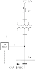
Calculation of Power Factor (PF) requires calculation of angle between voltage (V) and current (I). PF is the cosine of the angle between V and I. Typical wiring diagram for PF controller is shown below. Depending on the manufacturer, the control voltage input and voltage measurement for the controller may be separate or same. PF controllers are usually capable of switching 6-12 stages of capacitor steps. When the measured reactive power exceeds the value of the smallest capacitor stage, PF controller will switch ON a stage and will continue to switch stages until the target PF is achieved.
Read: Reactive power measurement
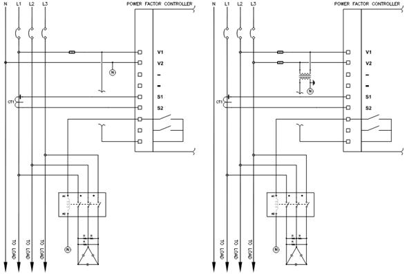
The coil voltage for the capacitor contactors (A1, A2 in figure 1) and the PF controller voltage measurement (V1, V2) MUST be derived from the same phase. This is to avoid contactor drop-off and multiple reconnections during a voltage sag. If an already charged capacitor is reconnected back to supply voltage without allowing time for capacitor discharge, then large magnitude voltage transients can appear.
Read: Capacitor bank discharge methods
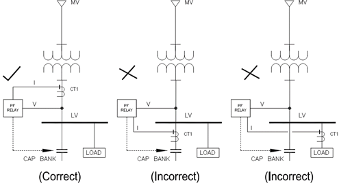
Current Transformer (CT) need to be placed at the service entrance panel ahead of all the loads and ahead of the capacitor bank. Only one CT is needed for PF controller applications. CT should NOT be on the capacitor bank feeder circuit or the load feeder circuit. CT should be sized based on the expected loading on the bus rather than the bus rating for better operational performance of the controller. PF controller will only maintain the target PF at the load side (downstream side) of CT installation towards where power flows.
Read: Wye and delta connection vector diagram
Two ways of connecting PF controller to the network are as follows:
- Voltage fed Line-Neutral & CT fed from the same phase
- Voltage fed Line-Line & CT fed from the third phase
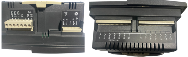
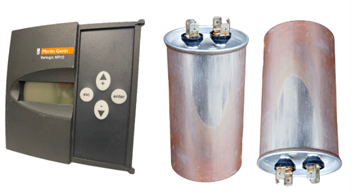
Figure 3 shows an example PF controller. The left picture shows typical voltage and current inputs (S1, S2). The right picture shows the capacitor switching contacts.
For the power factor relay to calculate PF, the voltage and current phasors can be offset at most 90 degrees. Depending on the relative location of CT and the voltage measurement phase, the PF controller needs to be fed with the correct compensation angles. Newer controllers may be able to calculate this automatically during the commissioning stage once the basic power system data is entered. Table 1 lists the compensation angle for a system that operates on the ABC or L1-L2-L3 phase sequence and with CT polarity facing the source.
Read: Phase sequence and phase angle
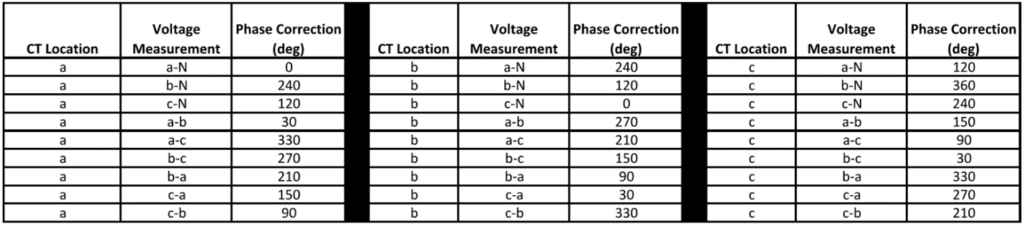
Diagrams below indicate three examples of how the compensation angles can be derived from the three phase vector diagram.
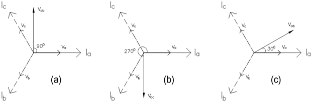
PF controller manual will usually list all possible combinations of voltage and CT connections and the corresponding phase compensation angle. When referring to the product manual, make sure the phase sequence the manual is based on is the actual system phase sequence.
Read: Power factor improvement and transformer loading
PF CONTROLLER WIRING FOR TRANSFORMER COMPENSATION
When CTs are placed on the secondary side of the power transformer as in figure 2, the reactive power drawn by the transformer will NOT be compensated. When it is desired to compensate for reactive power consumed by the transformer AND the connected LV load, CTs need to be placed at the primary side of the power transformer. If primary side voltage transformers (VT) are available, then this will be similar to any typical PF correction application. However, when primary side VT is not available, current can be fed from the primary CT while the voltage signal can be obtained from the secondary side VT. This type of measurement is also known as ‘mixed measurement’.
Read: Transformer reactive power consumption
When mixed measurement is done, the phase shift introduced by the transformer needs to be compensated in the PF controller. Different winding configurations produce different angle shifts, and users need to study the individual transformer on a case-by-case basis.
Read: Transformer connections: Phase shift and polarity
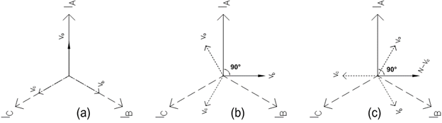
For a DD0 transformer, secondary voltage will be in phase with primary current. Voltage measured across the secondary side VT with VT connected to ‘Va-N’ will be in phase with the primary A phase current. No further compensation is needed in this case as seen in figure 6 (a).
For a DY11 transformer, secondary voltage will be shifted from primary by 11*300 = 3300. To get a 900 angle difference between voltage and current, the secondary voltage has to be measured across Vb-N as shown in the vector diagram in figure 6 (b). CT is assumed to be connected to primary phase A. In this case the angle compensation is 900.
Read: Voltage swell due to line-ground fault
For a DY1 transformer, the secondary side will lag the primary by 30 degrees. As figure 6(c) shows, to get a 90-degree angle difference between voltage and current, the secondary voltage has to be measured across N-Vc. CT is assumed to be connected to primary phase A. In this case the angle compensation is 900.
Read: How to calculate the reactive power of a a transformer?
When the connection is made as shown in figure 5, reactive power drawn by the transformer AND load will be compensated by the power factor controller. When mixed measurement is used, the voltage entered in the C/k calculation should be the voltage at which CT is measuring current. Another option available with modern PF controllers is to add ‘offset power’ to account for reactive demand that cannot be directly measured.
PF CONTROLLER WIRING FOR SYSTEMS WITH MULTIPLE SOURCES
When multiple sources are connected to a bus, the power factor controller needs to ‘see’ current from each source. A method to accomplish this will be to use a summation current transformer (CT). Some examples of summation CT can be found here and here.
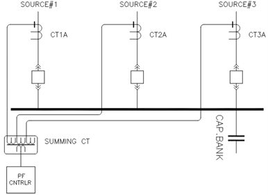
Consider three CT with a 1000:5 ratio fed to a summation CT with three inputs. Assume the summing CT ratio is 5+5+5:5. With three summation CTs, the effective CT ratio will become 3000:5. PF controller will calculate the effective PF of the entire system and inject the required Vars. Voltage reference to PF controller needs to be from the bus side and not the source side of main breakers.
Read: AC voltage drop and system power factor
PF CONTROLLER WIRING FOR SYSTEMS WITH TIE BREAKERS
When multiple sources and tie breakers (bus couplers) are involved, the situation becomes a little bit more involved. Assuming the tie breaker is closed normally, one might assume one capacitor bank is only what’s needed, and that’s not true and could lead to some issues. Assume in figure 9 that only the A side capacitor bank is installed and CT from both sources (CT1A & CT2A) are wired through summing CT to a single PF controller. Under this condition, when the tie breaker is opened, reactive power to the right of the tie cannot be compensated. To make things worse, the PF controller calculates that a higher amount of reactive power demand (due to both source CTs being summed) and will inject larger Vars than necessary. This could lead to overcompensation and voltage rise on the left side of tie breaker.
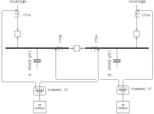
The preferred method to connect the capacitor bank in electrical gear with tie bus coupler is to provide individual compensation at each section as shown in figure 9. Voltage reference to PF controller needs to be from the bus side and not the source side of main breakers. If all three breakers can be closed at the same time, then summing CT is needed, and if only two of three breakers can be closed at any given time, CTs can just be connected in parallel.