Synchro check or sync check relays are used to verify that voltage, phase angle, frequency and phase rotation across two sides of a breaker are the same prior to closing the breaker. Synchrocheck relays ensures that bus and line side voltages are within programmed differentials of voltage magnitude, phase angle, frequency and phase rotation is the same. The permissive from this relay can then be used for either manual or automatic source paralleling. Out of ‘sync’ closing can create significant impact on the power system and in worst case can damage the equipment due to high short circuit currents. The sync check relay is ANSI element ‘25’.
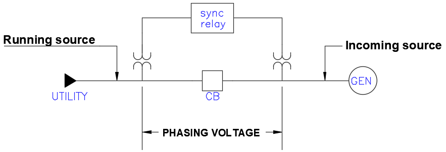
The basic method of synchronism check in a modern digital relay is shown in the figure below. Three phase input (running source) from one side of breaker is fed to the three-phase voltage input of the relay. A separate single-phase input from the other side of the breaker is used to provide the ‘sync’ voltage input (incoming source) to the relay.
Incoming source sync phase can be any of the three phases-A, B or C. Usually A phase is chosen and sync phase is a selectable parameter in modern digital relays. In addition, modern relays also allow for phase-phase connections or custom phase angle selections. Cases where (Incoming voltage) Vs cannot be in sync with running voltage Vp are:
Relay running voltage is connected to wye PT while the incoming sync input is connected phase-phase
Relay is connected to delta PT while the sync input is phase-neutral.
Sync input is beyond a delta-wye transformer.
For cases above a custom phase angle can be chosen when the sync voltage input always leads or lags the three-phase voltage input.
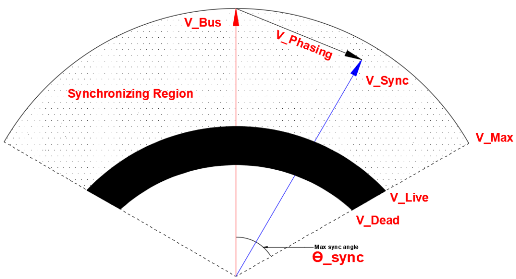
The difference in voltage between the two sides of the breaker is known as phasing voltage. For two systems to be synchronized, following conditions must be matched: Voltage, Phase Rotation, Phase Shift, Frequency.
In addition, the system either has to be either both three phase or both single phase.
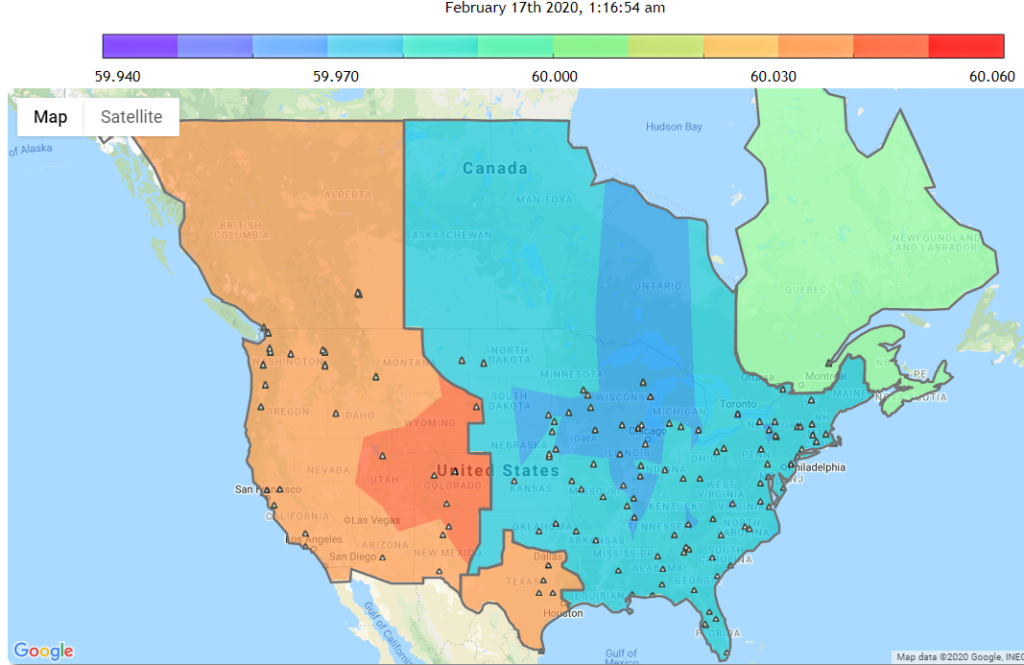
The frequency gradient map below shows the frequency deviations of power frequency (60 Hz) across the North America for the given time.
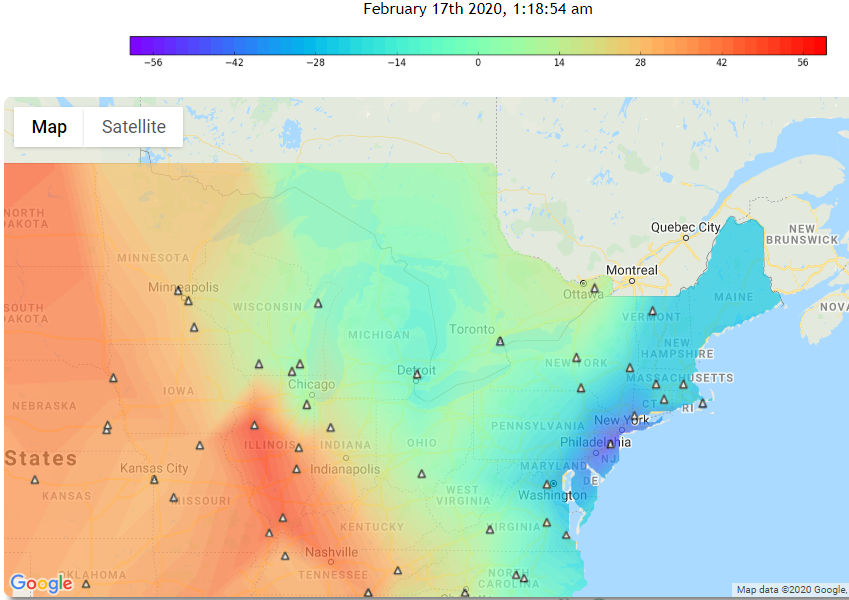
The angle contour map below shows the real-time phase angle differences of power system frequency (60 Hz) between various regions across continental US for the given time. Reference point is in Eastern Interconnection.
Voltage
Two sources that are to be paralleled ideally need to have the same voltage. If two sources with unequal voltages are paralleled it causes reactive power (Var) to flow between the sources. Minor variations (1-5%) in voltage can usually be tolerated. The var flow is due to the nature of interconnecting generators. The equation for reactive power flow between two sources assuming the phase angle difference is zero is given by:
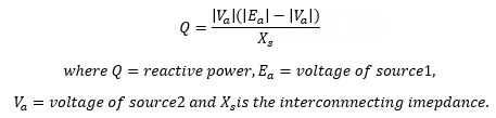
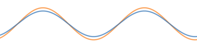
As can be observed, more voltage difference exists between two sources the more reactive power will flow between the two. Waveform shows two waves with same frequency and phase, but different voltage magnitudes. Var flow will cause unnecessary heating in interconnecting components. It is preferred that voltage of two sources be as close to nominal as possible to avoid reactive power (var) flow.
Phase Rotation
Two sources that are to be paralleled need to have same phase rotation ie, either both ABC or both ACB phase rotation. Opposite phase rotation can cause significant short circuit current during paralleling and should not be attempted. Phase rotation meter or the power meter connected to the panelboard can be used to check phase rotation prior to paralleling sources.
Read Phase Sequence and Phase Angle
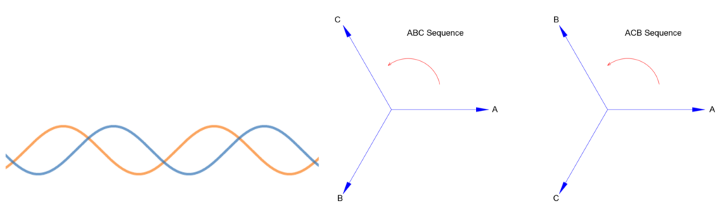
Above waveform show voltage waveforms for B phase for ABC vs ACB rotation. Vector diagram for ABC and ACB rotation are also shown.
Phase shift between two sources
Even with both sources having the same voltage and rotation, there could be a steady state phase shift between the two. See the figure below for example. Both the waves have same amplitude and frequency but has a steady state phase shift.
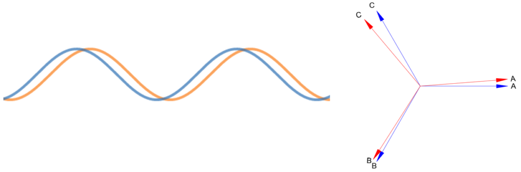
The ideal phase shift to parallel will be zero though that is not usually practical. Typically phase angle limits for paralleling two sources are ±10 degrees or less. The practical effect of paralleling two sources with different phase angle is that exchange of real power (watts) happens. Equation of real power exchange between two sources is given by:
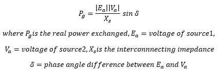
If the phase shift between two sources is zero, no real power exchange takes place between two sources, which is what we want. We want power to flow to the load and not between the sources.
Frequency
Though most utility sources have fairly stable frequencies of 60 or 50 Hz sometimes one source may have a slightly higher or lower frequency. This could happen if the generating station is an islanded source or if the power is from a local standby generator.
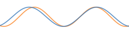
If one source has a slightly higher frequency, then the sources may come to perfect synchronization for brief time and then ‘slip’ away in to not being synchronized. Picture shows two waves with slightly different frequencies.
If two sources with different frequencies are closed, real power (watts) flow between sources which will vary depending on the relative phase angle difference between the waves. Since the frequency (and hence speed) of once source is slightly ahead, phase angles keep changing throughout and hence the real power exchange also keep varying. Practical limits to frequency difference for paralleling two sources are generally 0.1 Hz or lower.
Below is an example of two waves with slightly different frequencies. As can be observed the waves come together with zero phase angle difference (IN SYNC) and then drift away (OUT OF SYNC) only to come back to sync after few cycles.
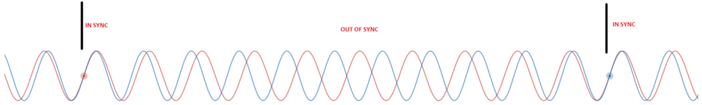
This would be the scenario when we try to synchronize utility power source with local diesel power generator. Generator frequency will likely keep ‘drifting’ and only at certain times does the utility and generator voltages come in to perfect ‘sync’. The breaker will have to close around this time (possibly using the anticipatory type phase angle method discussed later in this article) after which the generator frequency will be ‘locked’ in to the utility frequency. If generator and utility are continued to operate in parallel, the generator frequency will keep following the utility source. Once the two are disconnected the generator frequency will likely drift again.
Synchrocheck Relay Settings
For successful synchronization, voltage, frequency, phase rotation and phase angle of the two sources must meet the thresholds set per the user programmable settings in the relay.
Voltage: Voltage settings for sync check relays have a voltage HI and voltage LO settings. If measured voltages across the breaker fall within this band then the corresponding relay word bits will be asserted (TRUE) indicating healthy voltage.
Frequency: If the voltages are found to be good in the step above, relay then calculates ‘slip frequency’ which is the difference of frequency between the running phase voltage (fp) and incoming sync voltage (fs) input.
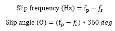
For example, if the running frequency is 60Hz and the incoming frequency is 60.1Hz the slip frequency is -0.1Hz and the slip angle is 360. This means that in a time period of one second, incoming source (fs) will zoom past running source (fp) by 36 degree. Or in other words the angular distance between running source and incoming source changes by 36 degrees in one second.
Frequency parameter to set in the relay will be ‘Max Slip Frequency’. If the measured slip is greater than the set value, the synchrocheck relay will not give permissive for breaker to close. While two utility sources should have very low slip (<0.005 Hz), a utility-generator or a generator-generator combination can have higher slip frequency threshold.
Phase Rotation: The phase rotation can be ABC or ACB. One way to program phase rotation check is to use ANSI 59Q (negative sequence overvoltage) element in the breaker close logic. If negative sequence voltage is detected (Opposite phase rotation will result in high negative sequence overvoltage) the breaker close logic will prevent breaker from closing.
Phase Angle: Phase angle settings for sync check relay is Max Angle. If the angle between the two sources is greater than this value, close permissive is not given. Within this there could be two options depending on the relay.
1)Non-Anticipatory Type: If the measured slip frequency is less than programmed ‘Max Slip Frequency’ (say 0.005Hz), relay assumes sources are ‘static’ and not ‘slipping’. In this case relay calculates the angle difference and if the angle is less than the ‘Max Angle’ setting the sources are flagged as being in ‘sync’. This is usually the case when two utility sources are paralleled since utility frequencies seldom drift more than few decimals.
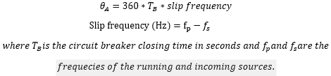
2)Anticipatory Type: If the slip frequency is greater than programmed ‘Max Slip Frequency’ (say 0.005Hz) relay assumes the sources are ‘slipping’ and takes in to account the settable breaker close time. This type of sync check relay has the added capability to give breaker close command in advance such that when breakers actually close, they close at zero-degree phase difference. Anticipatory type relays calculate the advance angle required to compensate for breaker close time by monitoring the slip frequency and the breaker closing time that is programmed (usually takes 3-5 cycles). This capability minimizes system transients.
High slip frequency is possible when a standby generator is being synchronized to utility or worse when two generators are being synchronized to each other. Anticipatory type synchrocheck relay closing is needed for these applications.
The angle to advance is calculated as:
Once the max closing angle (Ɵ_sync) is programmed, the relay has a window of (2*Ɵ_sync) for closing the breaker as shown below. If measured voltage is less than V_live in the black shaded region, no synchronism check is carried out.
Calculator below can be used to get the idea of real and reactive power flow between two sources when paralleled. Note that this calculator is just built so that the user can get grasp of the fundamentals. The interconnecting impedance is fixed at 2pu. Practical power flow calculation requires lot more data and actual interconnecting impedance.