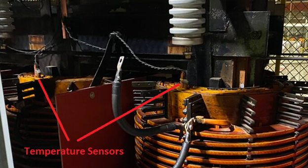
Temperature is the most common cause behind power system device damage. Expensive devices such as motors and transformers can have insulation life reduced by half if the operating temperature is increased by 100 C. Surface temperature of modern induction motors is around 300C lower than the insulation. For a class F motor that can run at 1550C will have a surface temperature of 1250C which is too hot for a human to touch. The older practice of touching the motor frame to estimate winding temperature is no longer practical. For this reason, it is imperative that methods to measure winding temperature is installed and reliable motor over temperature monitoring relaying is implemented during commissioning phase for accurate thermal monitoring. The most popular method to measure motor stator temperature is to insert Resistance Temperature Detectors [RTD] in to the winding slots. RTD standards and tolerances are given in IEC 60751.
RTD is a passive device for which the resistance varies as its temperature changes. An external electronic circuit is necessary to measure the change in resistance which is usually accomplished by passing a small current of around 1ma-5ma and measuring the voltage drop.
RTDs can be used for transformer temperature monitoring though thermocouple-based measurement is more commonly seen in transformers.
Link to Motor starting calculator
RTD Basics
RTD uses the principle that the resistance of an electrical conductor varies depending on the temperature. It is very convenient to use resistance to detect temperature (instead of micro volts as in thermocouple). Regular copper wires can be used between RTD sensors and instrumentation. The most commonly used RTD in the industry is the PT100. This sensor is made of platinum and has a resistance of 100Ω at 00C with a temperature coefficient of 0.00385. There are also PT500 and PT1000 types which has resistance of 500Ω and 1000Ω at 00C.
Platinum RTD resistance and temperature relation above 00C can be expressed as:
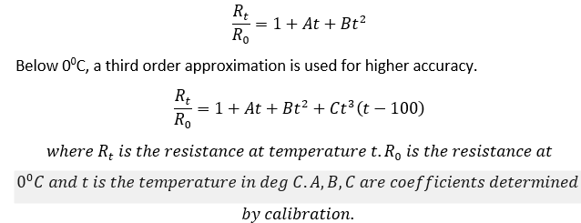
IEC 60751 industrial RTD standard gives the value of the coefficients as A=3.90802 x 10⁻³, B= -5.802 x 10⁻⁷ and C=-4.2735 x 10⁻¹².
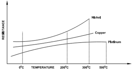
There are several metals such as copper, gold, nickel, platinum, silver that can provide predictable and stable resistance vs temperature relationship. Of these, copper, gold, nickel, silver has low electrical resistivity making them unsuitable. In fact, copper does have linear relation between resistance and temperature but is prone to oxidation and is only used in moderate temperatures and less accurate applications. This leaves platinum which has many advantages, some of which are:
- Platinum is a noble metal.
- High resistivity.
- Well understood (though not entirely linear) resistance vs temperature relation.
- Platinum can be obtained in pure form.
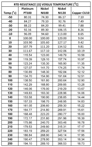
Resistance vs temperature for Platinum, Nickel and Copper RTDs are given in table 1.
Read: Motor differential protection
RTD Connection Types
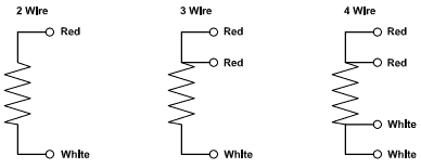
RTDs can be connected in two, three or four wire configurations. Of these, three wire is the most common connection method.
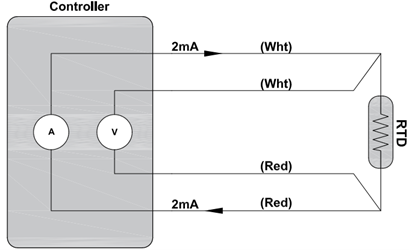
Four Wire RTD: Four wire RTD has the most accuracy when compared to other two methods. Four wire RTD cancels all errors due to length and resistance imbalance between the leads. Current is passed through outer two leads and the voltage drop across RTD is directly read as shown in figure 5. Resistance or voltage drop on the lines become insignificant and does not affect measurement accuracy in this method.
Since four wire RTD resistance is directly read from the unit, wire gauge need not be as thick as 2 or 3 wire RTD. For applications requiring high accuracy, corrosive environments and with sensors installed far from receiving device, this method can be used.
Having to install four wires makes the installation more expensive, cumbersome, and prone to wiring error. Four wire RTD are not very common in the power industry.
Read: Overcompensation of reactive power for induction motors
Three Wire RTD: Three wire RTD has a built-in compensation loop that the controller uses to remove lead resistance from the calculation. Controller first measures resistance between two red leads (hot & return) and then resistance between white and red leads (compensation & return) which is nothing but the resistance of interconnecting wire between controller and sensor. Assuming all three wires are of same length, subtracting first measurement from second gives the sensor resistance. Three wire RTD is the most common type of temperature measurement, and it offers a good combination of precision and ease of use.
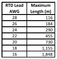
Three wire RTD usually have a loop lead wire resistance limitation of 25Ω (controller dependent) for platinum and nickel and 3Ω for copper RTD. Table 2 lists maximum RTD lead length (per lead) to have 25Ω.
Let’s see how three wire RTD compensates for lead resistance.
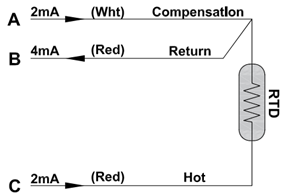
Temperature controller sends a constant current (usually less than 5ma) through leg A and C and return current flow through leg B. Referring to figure 6, the voltage drop along this circuit can be calculated as:
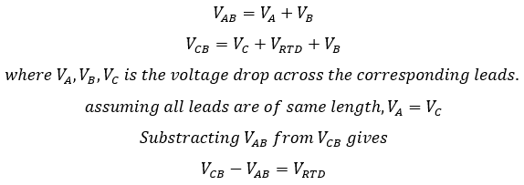
Above equations show how a controller would electronically subtract two voltages to negate the effect of lead resistance.
Two Wire RTD: Simple two wire RTD is used when high accuracy is not required. Drawback of this method is that the resistance of connection lead is always included in the measurement. Usually, the limiting distance for this type of connection is around 300ft (~90m) above which error become significant.
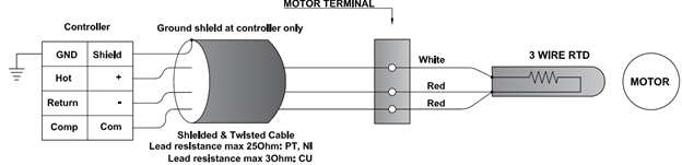
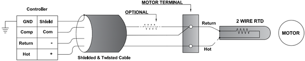
For some older motors there may be only two wire RTD available. In those cases, three wire RTD controller can be used and wired as shown below to compensate for the lead length. A compensation lead is added to compensate for the resistance of hot and return conductors from motor terminal to RTD. This is assuming all cables have equal length and hence resistance. Note that if the distance between motor and motor RTD terminal is small, compensation resistor is optional. If this distance is significant then a resistance corresponding to wire length between motor terminal and RTD may be added. This is a quick and easy way to connect older motors with two wire RTD with modern three wire RTD controllers.
RTD Extension Cables and Color Codes
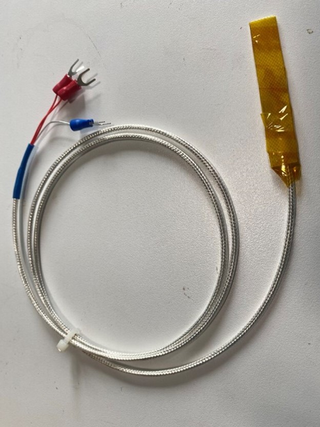
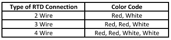
Two wire RTDs have red and white wires. Three wire RTDs have two red and one white. Four wire RTDs have two red, two white wire.
Typical three wire RTD cable comes with three stranded, silver plated, insulated conductors with an overall braid to prevent electromagnetic interference. There are also cables with 1, 2, 4, or 6 conductors available.
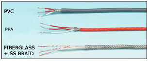
RTD cable extensions are not as critical as in thermocouple cables. The main consideration in RTD extension cable is to have a low resistance and interference free connection between sensor head and instrumentation. Connectors on RTD cables can be used if resistance is kept low, and resistance introduced is same on all wires. Some considerations while using RTD extension cables:
- Keep the lead resistance per lead below 25Ω (Platinum and Nickel RTD) and 10Ω per lead for copper RTD.
- Use shielded twisted cable for RTD extension to prevent noise pickup.
- RTD should not be installed adjacent to high current carrying wires.
- RTD extension cable shields are usually internally grounded at the meter or digital relay (check the manual). Avoid grounding shield at multiple locations to avoid circulating currents and noise pickup.
How to test an RTD?
If the type of RTD (PT100, NI120 etc.) is known, then resistance value can be read directly using a multimeter. Values can then be compared to table 1. Most common failure mode of RTD is to have an open circuit, though short circuit is also possible. Repeated heat and cool cycles, contamination, moisture, vibration all can lead to RTD failure over time. It is important for the controller to recognize open or short RTD and initiate suitable alarm. Other methods to minimize nuisance RTD trip is discussed in this article.
On the controller side, a quick way to test is to insert passive resistors to simulate temperature.
Link to Motor current calculator