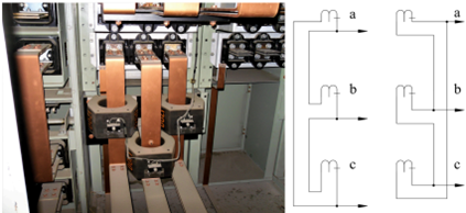
Current transformers [CT] for metering or relaying can be connected in wye or delta fashion. In today’s power system, wye connection of CT is almost exclusively used. Delta connection is only encountered when upgrading older installations or when user requirements specify having delta connected current transformers. This article discusses the basics of delta connection CT and lists some of its applications and characteristics.
Main application of delta connected CT is to eliminate zero sequence current from entering protection relays and to provide winding angle compensation for electromechanical relays. Delta connected CTs can also be used for metering application, though under unbalanced loading condition there will be some accuracy issues due to zero sequence blocking nature of delta connection.
Important considerations for delta connected CTs:
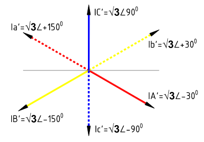
- Delta CT current output is not just primary current divided by CT ratio (CTR); Instead, due to delta connection, CT output current will be √3 times primary current divided by CTR. If the connected meter or relay cannot compensate for this √3 multiplier, delta connection should not be used. See figure 8.
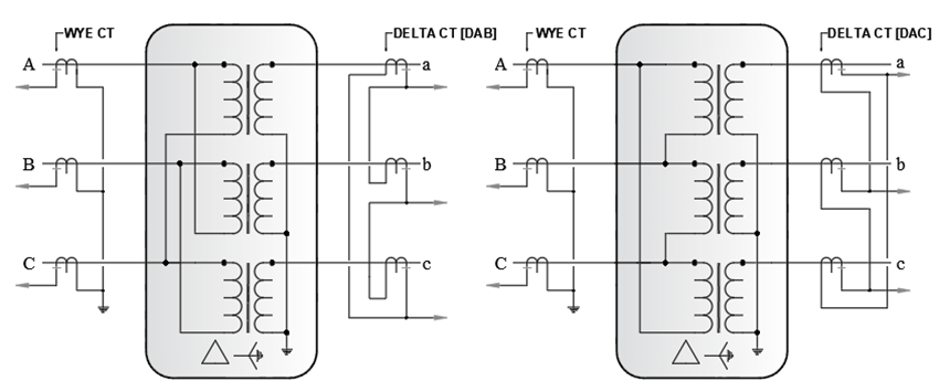
- Delta CT output current phase angle will differ from primary current phase angle according to the type of delta connection DAB or DAC). See figure 6.
- Delta connected CT blocks zero sequence current from entering the connected meter or relay. Zero sequence current in the primary circuit will not be present in the delta connected CT secondary line current. Zero sequence current will only circulate within the closed delta. For balanced load condition this is not a problem as there is no zero sequence present. However, during unbalanced condition, this can lead to metering errors (if delta CTs are used for metering).
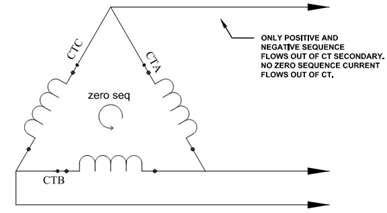
- Since delta connected CT blocks zero sequence current, it lends itself well to differential relaying as we do not want out of zone ground faults to appear as differential current in a wye connected transformer.
- Delta connected CTs can be used for providing winding angle compensation across delta-wye or wye-delta transformers.
Read: Wye and Delta connection vector diagram
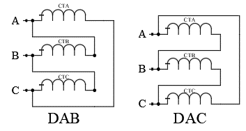
Delta CT connection can be done in two ways, DAB or DAC sequence. For transformer differential application, delta CT connection is done to match the corresponding transformer delta closing.
Read: Transformer connections: phase shift and polarity
Figure 4 shows transformer with primary in wye and secondary in delta. If we follow the pattern of delta closing, it can be seen that this is DAB type.
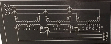
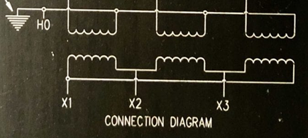
Figure 5 shows transformer with primary in wye and secondary in delta. If we follow the pattern of delta closing it can be seen that this is DAC type.
Read: Zero sequence current transformer
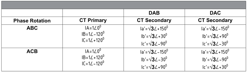
Due to delta connection of CT, there will a ratio and angle difference between primary and secondary current. Figure 6 shows CT secondary current for CT with 1:1 ratio with ABC and ACB phase primary current rotation. Secondary current will be the primary current divided by CT ratio (1 in this example) and then multiplied by √3. Angle of secondary current will be offset from primary line current based on type of delta (DAB or DAC).
Read: Series connection of current transformer
For modern digital relays, once the CT type (wye or delta) is programmed in the relay, relay software will account for the √3 multiplier. Phase angles displayed will be offset unless the relay has option to enter the type of delta connection (DAB or DAC) or enter the compensation angle. During unbalanced load conditions, it is not possible to reproduce primary current accurately since delta connection will block zero sequence components. For metering applications this could lead to small error.
Read: Three phase current metering using two current transformers
Delta connected CT for transformer differential application
For older electromechanical relays, delta connected CTs were used for phase angle compensation. For example, a Delta-Wye transformer will have 300-angle difference between primary and secondary (with HV side leading LV according to ANSI standards). Differential relay needs correctly phased current inputs so that delta-wye angle difference does not cause false differential trip. Delta connected CTs are used on the wye side of transformer and wye connected CT on the delta side of transformer in such cases. See figure 7.
Read: Phase sequence and phase angle
For a delta-wye transformer, if the CTs are delta-wye between primary and secondary respectively, then any external ground fault on secondary (Wye) side will cause current to flow through wye connected CTs. Corresponding primary current will circulate within the transformer delta winding. Delta connected CT on the primary will not ‘see’ this current resulting in differential trip. This trip is not desired as it is ‘external’ to the transformer differential zone. For this reason, a delta-wye transformer needs to have a wye-delta connected CT for correct current phasing for both internal and external faults. For in-zone ground faults, the positive and negative sequence current components are sufficient to initiate differential trip. The type of CT wiring (DAB or DAC) is based on type of transformer delta closing.
Read: Transformer differential protection
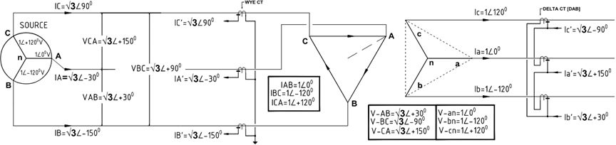
Figure 8 shows the voltage and current on a delta-wye transformer and the corresponding CT currents. CTs at primary are connected in wye and on secondary its connected in delta.