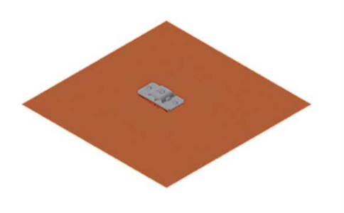
Different means of achieving low earth or ground resistance are to drive ground rods, bury wire, copper strip, ground plate etc. In this article, ground resistance of buried ground plate is discussed. Buried plate electrodes are usually square or rectangular but can also be circular shaped. Plate electrodes provide large surface area to dissipate fault current in to ground. Grounding plates are commonly used where thickness of top soil is very thin such as in rocky areas which makes installing ground rods difficult or even impossible. When available space to bury grounding electrode is thin, grounding plates offer decent option to increase effective surface area for reducing ground resistance.

Grounding plates can also be used for temporary grounding of portable generators, fences, mobile equipment etc. as the plate can usually be easily retrieved for later use. Grounding plates are installed horizontal to ground but can also be installed vertically for easy retrieval.
Read: Estimating substation ground grid resistance
Common grounding plate thickness is 0.032 inches [UL96 compliance] to 0.064 inches [UL467/NEC compliance]. Some examples of plate dimensions are (in inches) 4×4, 12×12, 24×24 etc. In metric system typical dimensions in mm are 600×600, 900×900 with thickness of 1.5mm or 3mm. Other sizes are also available depending on manufacturer. Plates are available with or without prebuilt pig tails or other attachment points. Ground plate can be made of copper, copper clad steel or steel.
Read: High impedance in earth ground wire due to magnetic field
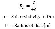
For a buried circular plate near soil surface, equation for effective earth or ground resistance [Rg] value is given by the following equation [Ref 1]:


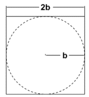
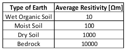
The following calculator can be used to calculate earth or ground resistance for a single buried square ground plate electrode. Since the above formula is for a circular disc, square plate is approximated as a circle for calculation purposes. Typical resistivity values as provided in IEEE Std 80 can be used or user can input soil resistivity data directly in to calculator. Since the conduction in soil is largely electrolytic, the amount of moisture and dissolved salts affects the resistivity of soil. Without actual measurement, accurate characterization of a particular soil as ‘wet organic soil’ or ‘moist soil’ is hard to define.
Read: Substation grounding: Role of crushed rock

A single ground plate seldom provides satisfactory resistance. Multiple plates may be installed and connected in parallel or supplemented with ground rods for better performance.
Read: What is separately and non-separately derived system?

Read: Single point grounding in power systems
Summary
Ground plates provide an easy solution for temporary grounding of portable installations such as generators, portable antennas, electric service vehicles etc. Ground plates can also be of help in areas with shallow soil where driving ground rod is a challenge due to bed rock. Ground plates can be easily retrieved after use. Achieving low earth resistance (<5Ω) with just ground plate is a challenge. Often additional plates need to be connected in parallel or other means pursued if low resistance is the goal.
Ground grid using buried conductors such as ground plates help to stabilize ground potential rise during fault condition.
Reference [1]: Power system grounding and transients; A.P. Sakis Meliopoulos
