Capacitor bank can hold dangerous voltage after disconnecting from power system unless discharging devices are connected to the capacitor terminals. IEEE Std. 18 standard requires capacitors be equipped with internal discharge devices to reduce residual voltage to below 50V in less than 1 minute for 600VAC and within 5 minutes for > 600V rms rated capacitors. IEC 60831 standard requires discharge to <75V within 3 minutes to prevent accidental injury by residual voltage.
Reclosing or switching ON capacitor bank with residual voltage in phase opposition can cause high inrush current which may damage capacitor, switching devices and create power system disturbance. In automatic power factor [PF] correction capacitor banks, steps are typically only reenergized after voltage is reduced to less than 10% of the rated voltage.
Resistors are the preferred discharge device for capacitors though reactors and voltage transformers can also be used if faster discharge is necessary. By using resistor, the rate of discharge, resistor power dissipation can be controlled to a high degree by the designer. Resistors are typically applied directly to the terminals or wired inside individual capacitor ‘cans’. Discharge resistors are also known as bleed resistors.
Link to: Power factor calculator
Basics of capacitor discharge
When capacitor is applied with AC source, the instantaneous voltage on capacitor varies depending on the applied instantaneous AC voltage peak. If capacitor is disconnected at the zero crossing of AC waveform, no voltage is stored and if capacitor is disconnected at the peak of AC wave, maximum voltage is stored. For discharge resistor sizing, we assume the worst case (capacitor disconnected at AC voltage peak).
Read: Power factor correction and transformer loading
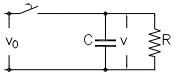
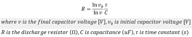
Key terms to understand when dealing with capacitor discharge is exponential decay and time constant which is the product of capacitance and resistance. Unit of time constant is seconds. The voltage profile of capacitor discharging in to a resistor can be written as:

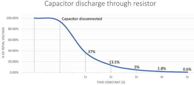
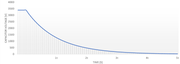
From the plot of capacitor discharge vs time constant [τ] we can see that the capacitor terminal voltage will decay to 37% of its initial value in one time constant and to 5% in three time constant (3τ) etc. Figure also shows that atleast five time constant (5τ) is needed to bring the voltage close to zero. Use of discharge resistor is not a substitute for the recommended practice of manually discharging residual charge before working on capacitors.
Read: Resistance of human body
For most power system switching applications, once the voltage is decayed below 10% it is typically safe for reclosing, switching etc.
Capacitor discharge methods
The most common method of power capacitor discharge is to permanently connect resistors across the terminals. Alternative less common way is to have a switched resistor, reactor or voltage transformer connected across the terminals. Three methods are discussed below.
1. Capacitor discharge using switched resistor
A fast way to discharge capacitor is to connect switchable low ohmic value resistor across capacitor terminals. When capacitor is disconnected from power source, an auxiliary relay connects capacitor terminals to resistor ‘r’ dissipating the charge across the resistor. See figure 3. Resistor ‘R’ is the built-in discharge resistance of the capacitors which is typically of high ohmic value. Each discharge generates heat in switched resistor thus limiting the number of switching operations.
Link to: kvar to uF calculator
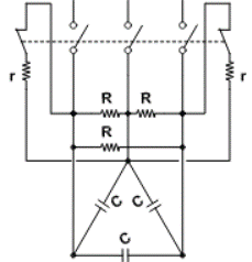
Switched resistors are used when faster capacitor discharge is necessary for applications such as providing compensation for rapidly fluctuating reactive load for cranes, hoists etc. With faster discharge, capacitor will be ready for reconnection in shorter time frame. Switched resistors are commonly used in low voltage (<600V) applications. In figure 3 only two switched resistors are used. This is known as V connection and is further discussed below in this article.
Read: How to identify capacitor switching transients
2. Capacitor discharge using permanently connected resistor
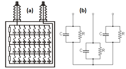
Easiest and most reliable way to ensure capacitor discharge is to permanently connect resistors across the capacitor terminals. As soon as power source is turned off, capacitor starts to discharge through the resistor. Discharge resistor can be externally connected or mounted inside the capacitor can. Downside of using permanently connected external or internal resistor is steady state power loss. Resistor heating needs to be factored in to while installing power capacitors in tight spaces with limited air circulation.
Link to: Delta-wye conversion calculator
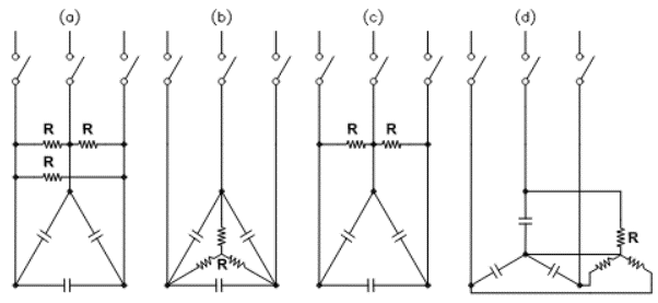
For three phase capacitors, ideally three resistors are required to discharge. For capacitor cans connected in delta, ‘V connection’ is commonly used which only requires two resistors as shown in figure 4 (c). Note that effective capacitance across each resistance in this case is not C but 1.5C due to delta connected capacitors.
Discharge resistance calculations
Discharge resistance R needed for a given time constant can be calculated as below:
Time ‘t’ required in seconds for initial capacitor voltage to reach a particular value ‘v’ can be calculated as:

Note: When doing calculation use appropriate phase-phase or phase-neutral voltage applied across capacitor. Depending on whether capacitors are connected in star or delta and type of resistor connection (see figure 4), the effective capacitance presented across resistor could be different from ‘C’.
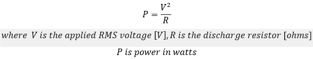
Power dissipation in discharge resistor
Permanently connected discharge resistors can become very hot (~ 2000 C) during continuous operation. Steady state power dissipation (loss) when resistors are permanently connected to capacitor is given by:
For three phase units, the above equation needs to be multiplied by three. Typically for low voltage capacitor banks, individual capacitor cans are connected in delta and for medium and high voltage banks preferred connection is star (wye).
For switched discharge resistors, power loss needs to be calculated based on above formula and considering the switching duty cycle. Since switched resistors are typically of low ohmic value the power loss and hence heat rise can be higher.
Read: Star and delta connection of capacitors
Medium voltage capacitors are often comprised of multiple internal strings of capacitors, internal fuses, and resistors. For power loss calculation it is required to calculate the effective discharge resistance and total capacitance.
3. Capacitor discharge using reactor
Traditional discharge resistors may take up to a minute for discharging capacitors at LV and up to 5 minutes at MV. For many applications requiring frequent switching, this time unacceptably long and another faster method would be preferred.
Link to: Inductance calculator
Capacitors can be rapidly discharged if reactors are connected across the terminals. Under normal power system frequency (50/60 Hz), reactor offers high impedance and hence minimal power loss. When capacitor is disconnected, stored DC voltage is applied across reactor. Ideal reactor offers zero impedance to DC voltage. In practice reactor will have built in resistance to limit the discharge current. Resistance of the reactor will be significantly smaller than a typical resistive discharge circuit thus enabling faster discharge.
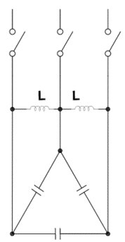
Due to reactor offering high impedance at power system frequency, only a low steady state current will flow through the reactor. Power loss and hence heat rise is thus greatly reduced. Heating of capacitor terminal is also reduced. Even though reactors enable faster discharge, manufactures have strict limitations on the permitted number of discharges per minute to prevent overheating.
Read: CT failure due to capacitor bank discharge
As an example, a particular manufacturer discharge reactor for 50kVar, 480V capacitor permits two discharges per minute at 400C with the reactor capable of bringing the terminal voltage below 50V in less than 15 seconds. Compare this to standard resistive discharge which could take 60 seconds to reach 50V.
Read: Wye and delta connection vector diagram
A similar concept uses voltage transformers [VT] connected across capacitor terminals for faster discharge. Inductance of VT provides high AC impedance for power frequency and once capacitor is disconnected, low DC winding resistance of the VT enable fast discharge. Though the concept is simple, the addition of VT requires considerations beyond the scope of this article.