Power Factor correction is accomplished by adding the required amount of capacitive VARS to the network to compensate for inductive VARS in the system. Engineers familiar with sizing power factor (PF) correction capacitor banks might have noticed that it takes relatively less capacitance to improve from 0.7PF to 0.75PF whereas the amount of capacitance needed to improve from 0.95PF to unity PF seems very large and out of proportion. Why is this the case, and what’s the underlying theory behind this? This article will discuss this topic.
Let’s study this topic by considering an example. Assume a facility with 1,000 kW of real power demand operating at a lagging PF of 0.8. To correct the PF to 0.85, it can be calculated that 130 kVAR of capacitor bank needs to be added, whereas to correct PF from 0.85 to 0.9 requires 135 kVAR which is slightly more than kVAR needed from 0.8 to 0.85. Now, more interestingly, if we need to improve PF from 0.9 to 0.95, then we need 156, and 0.95 to 0.99 requires 186 kVAR of PF correction. As can be seen, correcting PF above 0.95 gets really expensive quickly.

In figure 1, reactive power (kVAR) correction needed for improving PF in increments of 0.1 is shown. As can be seen, once the PF reaches around 0.95, the relation between additional reactive compensation and PF improvement is no longer linear. As such, the equipment costs tend to increase non-linearly if correction to unity PF is attempted.
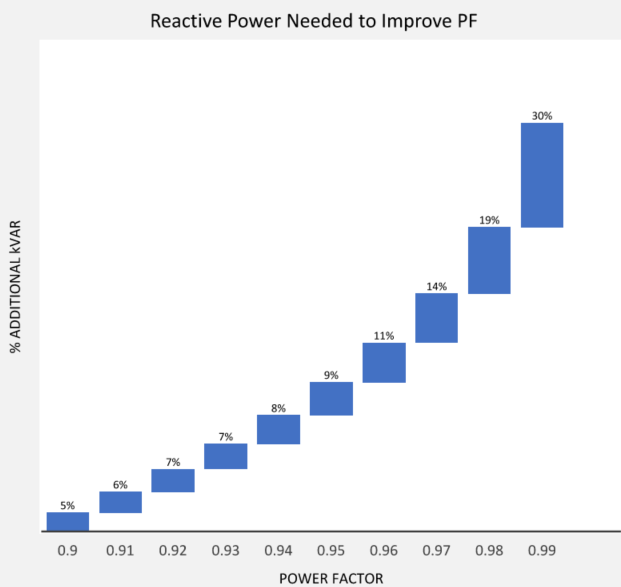
Figure 2 shows the % additional reactive power needed to improve PF from 0.9 all the way to unity for a normalized system. As can be seen, improving PF from 0.9 to 0.91 requires only 6% additional correction, whereas correcting from 0.98 to 0.99 requires 30% additional kVAR in PF correction.
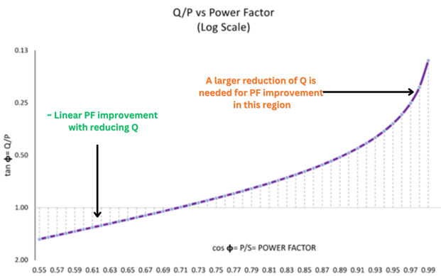
Figure 3 shows the trajectory of Q/P [tan𝞍] for various PF [cos𝞍] values. From the graph it can be seen that for an assumed constant real power (P) load, as Q/P is reduced (meaning Q is reduced my means of adding reactive compensation), PF improves almost linearly from, say, around 0.55 to 0.9. After 0.9 PF, the curve is no longer linear and is flatlining, which means a larger reduction in Q is needed to achieve further (small) PF reduction. Under normal conditions, real power ‘P’ is constant, and the only variable under customer control is the amount of capacitive VARs ‘Q’ that is injected.
Power Factor improvement and transformer loading
Return on investment for the additional correction beyond 0.9 or 0.95 is usually not good considering additional equipment and installation costs.
AC voltage drop and system power factor
In addition to exponentially increasing costs for correcting PF beyond 0.95 to unity, there are other disadvantages, such as the risk of overcompensation of reactive power. When a capacitor bank is sized for unity (PF=1), any load variation can cause the system to go into leading PF (PF>1) which can cause overvoltage, resonance, and equipment damage. To prevent resonance, step size of the capacitor bank needs to be small, which further increases the cost of the correction bank. The other option is to correct PF close to unity by using a synchronous condenser or active power factor correction equipment. Active PF correction (APFC) equipment consists of electronic devices capable of precise injection of reactive power and will maintain PF at the value programmed. There is also no risk of overcorrection or harmonic resonance with APFC, however, these are more expensive.
Electric utility companies for the vast majority of cases only ask customers to correct PF to 0.9 and rarely to 0.95. Considering this, typically there is no valid economic reason to size the capacitor bank for unity PF. Most customers get significant savings by correcting PF to 0.9, with further improvement above 0.9 coming with a noticeable financial burden. Cost benefits for most installations do not support PF correction to unity. The only exception to this is if the utility charges the customer for kVARh consumption, which is not common. Even if utility charges for kVARh, a cost-benefit analysis of correcting beyond 0.9 or 0.95 needs to be done to ensure a positive return on investment (ROI).
How to wire a power factor controller?
Conclusion
Correcting power factor to unity is expensive, as the graph of reactive power vs PF curve flatlines as it gets closer to 0.95 and beyond. To achieve improved PF beyond 0.95, a larger addition of reactive Vars (by means of additional PF correction capacitors) is needed compared to PF improvement below 0.95 (for example PF 0.8 to 0.9) where the improvement is somewhat linear and addition of capacitive vars will give an almost linear improvement of PF.
Power flow and voltage stability on AC transmission lines
Correcting PF beyond 0.95 gets exponentially more expensive. Most utilities only ask for correction to 0.9 or 0.95. In a typical industrial environment, there is diminishing economic benefit to correct beyond 0.9. The only exception to this is if the utility charges the customer based on kVAR consumption, in which case a cost-benefit analysis of correcting PF to 0.95 or 0.98 can be performed.
Correcting PF to unity also brings additional risks such as overcompensation, harmonic resonance, and overvoltage.