Power capacitor bank switching at utility or industrial power system can lead to current and voltage transients and can be detrimental to sensitive loads (drives, UPS) in the facility.
Often the facility engineer captures disturbance on a power quality analyzer but is not sure what exactly is he looking at. Below is a disturbance captured on a power quality meter. Now, how do you identify if this is caused due to power capacitor bank switching or something else. This article goes into this detail.
Capacitor bank switching can lead to some interesting power engineering issues. Some of the issues are energization inrush (discussed in this article), Back to back switching, Outrush current, Secondary resonance, Transient Recovery Voltage (TRV) etc.
Todays modern power meters and power quality analyzers have capability to identify capacitor switching disturbance and direction if they are programmed correctly. It is encouraged that customers use this feature to their advantage.
Energizing a single capacitor bank
When a discharged capacitor is initially connected to power system there will be a sudden voltage dip. This voltage dip will be a function of source impedance. Voltage will then recover in a low frequency oscillatory manner with peak voltage that can theoretically approach 2pu of bus voltage.
Low frequency oscillations due to capacitor switching can propagate through power distribution system far and wide depending on damping of the power distribution system. The oscillating voltage can:
*Couple across low voltage transformers.
*Damage or cause over voltage shutdown of drives and other sensitive loads.
*Can result in UPS switching to battery power unnecessarily.
*Surge suppressors can conduct and fail quickly.
*Multiple zero crossing of voltage waveform can result in process disruptions.
*Transformer damage (due to part winding resonance).
Following are the characteristic signatures of capacitor switching. Note that all of these may not be present all the time. If capacitor switching occurs at an electrically distant location, many of these characteristics will be attenuated heavily.
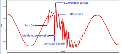
a) Presence of an initial ‘Step’ change in voltage
When a capacitor is initially switched on to bus, the voltage at the point of connection will have a step change (usually towards zero volts). The step change in voltage is a function of source impedance behind the bus. If source is stiff (low source impedance) then the voltage will be pulled ‘deep’ towards zero. If the source is weak (high source impedance) the voltage will only have a small step change. This can be clearly seen in the oscillograph above. Sometimes contactor or vacuum breaker contact bouncing can result in additional (usually worse) switching transients. This contact bounce also can be seen in the picture above.
b) Presence of recovery oscillatory waveform
Immediately following step voltage change, recovery oscillation starts. The frequency of this waveform depends on relative values of inductances and capacitances in the system (this topic is discussed later in the article). Typically, frequency of oscillations is usually few hundred hertz and sometimes slightly higher (~1-2Khz) depending on size of capacitor and system impedances. Large capacitor banks result in low frequency ring wave transients while small banks result in higher frequency transients. The initial peak of the voltage can have magnitude of up to 2 per unit (pu).
The duration of low frequency oscillations depends on system X/R ratio at capacitor bank. High X/R ratio results in long oscillations while low X/R ratio result in short duration oscillations. Typically, this means that capacitors that are switched at higher voltages (higher voltage typically has high X/R ratio) can prolong the oscillations. Capacitor switching at low voltage (<1kV) applications has low X/R ratio (high damping) and results in quickly damped waveform.
Note that oscillations can result in multiple zero crossings of the voltage waveform though this may not happen in all situations.
c) Voltage rise
Immediately following capacitor bank switching, we can observe a small magnitude increase in the bus voltage. This is a tell-tale signature to identify if the waveform is actually capacitor switching. Similarly, when capacitor is disconnected, we would expect a small reduction in bus voltage.
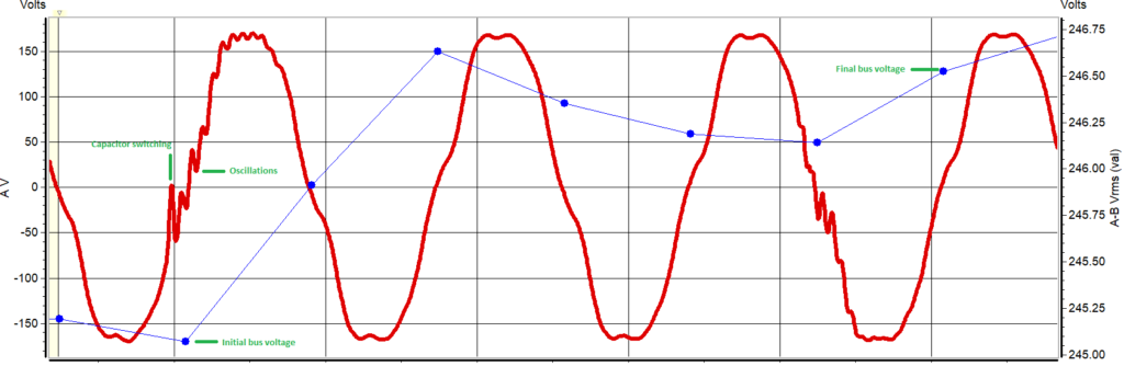
Graph above shows bus voltage increase after utility capacitor switching. This voltage increase is a positive indication that the oscillatory transient seen in the waveform is originating from capacitor switching.
c) Transient waveform is recorded at a predictable day and time
Though not necessary, utility capacitor switching usually occurs at predictable time of the day. If a particular drive or sensitive electronic equipment malfunctions at a particular time of the day, then utility capacitor switching can be a contributing factor and should be investigated.
d) High surge counts on SPD or SPD failing
Though not the necessary, periodic capacitor switching can trigger surge protective devices (SPD, MOV) to conduct due to transient over voltage. If SPD has a surge counter that shows high surge count or otherwise fail quickly then capacitor switching can be a contributing factor.
e) Variable speed drives shutting down on over voltage or DC bus overvoltage
Low frequency oscillatory waveform resulting from capacitor switching can charge front-end DC bus capacitors of drives and cause drive shut down on DC bus over voltage.
A solution to mitigate VFD shutdown due to capacitor switching is to add line reactor or isolation transformer.
Read: Line Reactor for VFD, Isolation transformer for VFD, VFD Over Voltage Fault
f) UPS switching unnecessarily to battery power
Oscillatory voltage waveform resulting from capacitor switching can be considered by UPS voltage sensing circuit to be ‘bad’ voltage or even over voltage. This results in UPS switching to battery power unnecessarily. Solution to this issue can be attempted by tweaking under and over voltage pickup setting of UPS.
Equations to calculate single capacitor switching transient
A simplified equivalent circuit of capacitor bank connected to a power system can be drawn as shown below. The equivalent ‘L’ is the inductance of the system from the point of connection towards the source (transformer if any plus utility source inductance). For simplified calculation, resistance may be ignored.
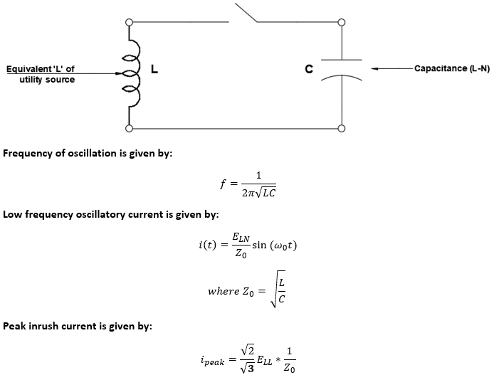
From the equations it can be noticed that as capacitor bank size (C) increases, peak inrush current increases while the frequency decreases. Similarly, if the capacitor banks size is decreased, peak current decreases while frequency will increase.
System damping has a significant influence in how far the switching transients will propagate. For medium voltage transmission systems damping will be low (due to low resistance) and transients can propagate over wide area. For low voltage capacitor switching, transients will be quickly attenuated due to high damping in LV systems.
Solutions to mitigate negative effects of capacitor switching transients
*Inform utility of disturbance that capacitor switching is causing in your facility. Utility may be able to time the switching or use some advanced methods like pre-insertion resistors or inductors to perform switching. They may also be able to do advanced zero-voltage switching of capacitor bank to prevent transients.
*On the facility side install line reactors for VFD/ VSD or install isolation transformers to prevent DC bus over voltage shutdown. Equipment sensitive to zero voltage crossing can also be made more robust by these methods.
*Tweak UPS voltage sensing logic to prevent unwanted switching to battery during utility capacitor switching.
*SPD or MOV’s are voltage clamping devices. These are considered sacrificial devices intended to clamp voltage to safe levels and protect downstream electrical infrastructure from switching transients and similar events. As such, consider installing additional ‘levels’ of SPD in the system. For example, install SPD at service entrance, distribution panels and at process load.
*If customer also has fixed or switched low voltage capacitor banks inside the facility in addition to utility owned capacitors (at MV level) then there exists a possibility of secondary resonance that can create some dangerous over voltage condition at the LV bus. This will need to be studied as the response will be unique to each installation. If this is determined to be a problem, the easiest solution is to turn off one bank. Alternative is to engineer the capacitor bank to avoid resonance condition.
Read: Power Factor Calculator, Star and Delta Connection of Capacitors