When a system has too many radial lines protection using time delay overcurrent relay becomes impractical. Time delay for relay closest to the source becomes excessive. This problem can be solved to an extent by using distance relays.
Distance relays uses voltage and current to calculate the impedance to the point of fault. Relay uses this information to decide whether the fault is within the zone or outside the zone. Impedance relays are also known as distance relays or ratio relays.

Some of the advantages of distance relays compared to traditional overcurrent relays are:
*Using traditional overcurrent relays for protecting long transmission lines, the time delay for the relay closest to the source has to be set very high to avoid nuisance trip. This is done to allow other downstream relays to clear the fault. Fault duration hence is prolonged.
*Distance relays use voltage to current ratio which is more sensitive than just using current.
*Selective and dependable tripping for line faults without need for a pilot channel.
*Simple time coordination across multiple distance relays.
*‘Reach’ of each relay can be controlled using local voltages and currents.
*‘Reach’ that is mostly independent from system and fault conditions.
*In loop systems with multiple sources coordinating time over current relays is difficult. This can be easily handled by distance relays as each relay is assigned ‘zone’ of protection.
Basic Principles of Distance Relaying
Consider a fault on a long transmission line at a distance ‘x’ from the location of the relay. The fault causes large magnitude current flow on the line. At the same time, the voltage of the line (measured at the location of relay) will be depressed (reduced). Distance relays calculates the ratio of voltage (V) to current (I) and calculates the apparent impedance.

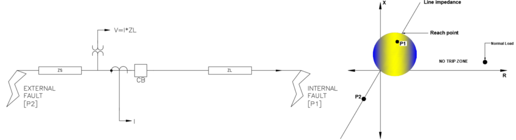
In relation to distance relays ‘Reach’ is a common term used. Reach defines how far down the line the relay detects the fault. For example, an 90% reach means the relay will detect any (solid three phase) fault between the relay and 90% of the line length.
Transmission line impedance plot
To understand the working of distance relays and many other relays, the concept of impedance diagram needs to be understood. Impedance diagram is nothing but a plot of impedance of the line from the view point of relay. Keep in mind this impedance is ‘calculated’ by the relay during a fault event as described earlier.
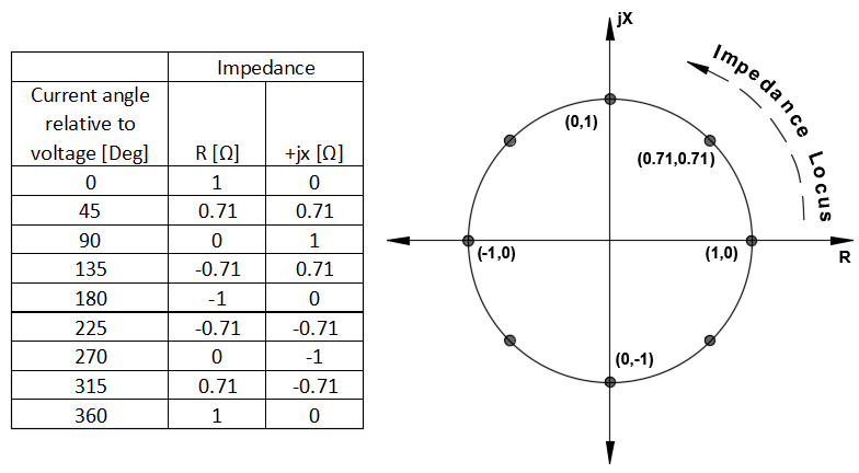
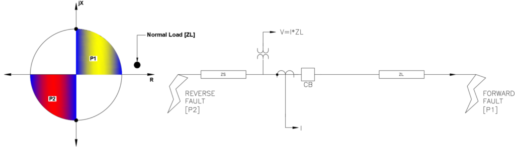
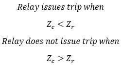
For faults in the forward direction, the ratio of V/I will give positive impedance and for faults in reverse direction the ratio of V/I will give negative impedances. If the impedance that the relay calculates falls within the distance relay impedance circle, then trip command is issued. For impedance outside the circle no trip is issued. Notice that a basic distance relay is not directional sensitive and is not useful for many common applications. This can be resolved by modifying the basic distance relay as discussed later in this article.
Note the location of ZL which is the normal load of the line. This will be the impedance seen by the relay when normal voltages and normal load current flows in the system. Note that this point will shift during a large current inrush due to motor starting, transformer energization and depending on the load power factor.
If you are wondering why the ZL is located close to x axis, it is because during a fault (high current) the dominant component is ‘inductive’. A plot of line impedance during a fault tend to be closer to the reactance (X) axis. Normal load on the line typically will have good power factor and tend to be more ‘resistive’ rather than ‘inductive’. Hence the load impedance is closer to the resistance (x) axis than to the reactance (y) axis and a fault impedance will be closer to reactance (y) axis than to resistance (x) axis.
Types of distance relays
From the example shown above, it can be observed that a simple distance relay is not sensitive to direction, which is a bad thing. For vast majority of applications, we need the relay to issue a trip when fault is in the ‘forward’ direction. Other common issues that protection engineers deal with are with load encroachment, highly loaded lines, need for custom trip characteristics etc.
Below are few variations of distance relay that takes the basic concept of distance protection and add specific features.
1.Distance relay in series with a directional relay
In this method a directional relay is added in series with distance relay to get directionality to trip characteristics. Alternatively, a mho relay as mentioned below can be used.
2.Mho type distance relay
Another option is to use a modified impedance relay (mho relay) which is obtained by offsetting the impedance circle and placing it in the origin. It is directional and more sensitive to fault currents lagging 60-85 degree than to loads that are near 0-30 degree lagging. Mho type distance relays are the most common type of distance elements used in transmission and distribution. Mho characteristic is inherently directional and also has some immunity against load encroachment. Load encroachment is the term used when load impedance moves in to the directional element zone of protection.
Consider a balanced beam arrangement that simulates a distance relay as shown below. V is the measured PT secondary voltage and I is the secondary current measured. Zø is the impedance.
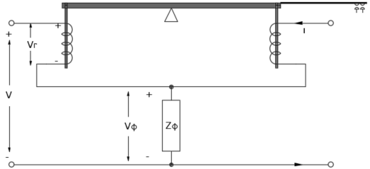
From the above figure, voltage Vr can be calculated to be:

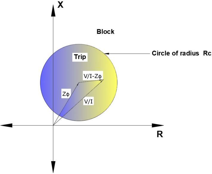
Where Rc is the reach impedance. Relay will trip is Vr/I is inside the circle with center Zø and radius Rc.
Advantage of mho characteristics is that we are free to move the center of the circle (by adjusting Zø). The resulting characteristic as can be seen in the figure is highly directional. The resulting characteristic is also known as offset mho characteristic.
The shape of mho circle can usually be further modified in modern digital relays to suit specific applications.
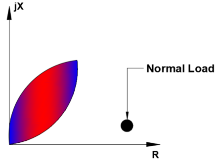
For example, if wide load swings are expected, a ‘lens’ type characteristic can be obtained. This characteristic will only issue trip when the fault impedance is very close to transmission line impedance.
Some relays also allow ‘tomato’ shaped characteristics to allow for more resistive faults in to the zone of protection.
3.Reactance type distance relay
This type of distance relay is used when the fault has a high ‘resistive’ component.
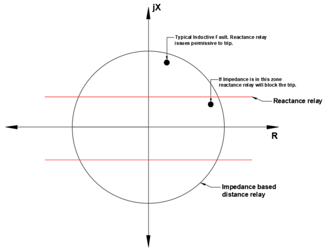
A large resistive load or an external fault can enter the zone of protection for a traditional distance element shown as circle. A reactance element can detect that as a highly resistive impedance and block the operation of the distance element. When the calculated impedance falls above the reactance relay characteristic, it is indicative of a highly inductive fault and reactance element gives permissive for the directional relay to trip. Reactance type element is almost never used on its own but used in series with other distance relays.
4.Resistance type distance relay
This type of distance relay is used when the fault has a high ‘inductive’ component.
A large inductive impedance means that there is very little resistance in the fault and the fault is probably within the zone of protection. Resistance type element is almost never used on its own but used in series with other distance relays or used as a permissive relay. The shape of the curve will look similar to the reactance relay except that the lines will be parallel to the ‘y’ axis.
5.Quadrilateral Relay
This type of relay curve offers the user ability to set custom resistive and reactive reaches to match the need of power system. Shape of such curve can look like a quadrilateral and hence the name.
Configuring distance elements
Modern digital relays can be programmed with line parameters such as positive and zero sequence line impedance (in secondary ohms) and the corresponding phase angles. Zero sequence source impedance and angle are also required.
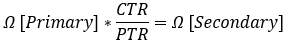
Line impedance values are typically entered in relay secondary impedance values. Primary line impedance can be converted to secondary values by following equation. CTR and PTR stands for CT ratio and PT ratio respectively.
Length of the transmission line is also required. After a line fault which leads to a distance relay operation, calculated distance to fault can be retrieved from relay and used for troubleshooting or fault repair.