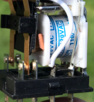
When current flow through inductive circuit is interrupted, voltage proportional to V= L (di/dt) is produced. This voltage can be many multiples of normal relay voltage. What prevents voltage from keep climbing even higher is circuit capacitance and contact arcing. This voltage is known as inductive ‘kick’ or inductive transient voltage and can cause contact arcing and eventual contact damage. This is a major concern in applications where electromechanical relays are used. Often surge suppression is required to assure reasonable contact life when relays are used to interrupt inductive current.
Consider a circuit shown below. When contact is opened, energy stored in inductor (given by 1/LI2) does not have any place to go and will charge stray capacitance of the circuit to a peak voltage given by:
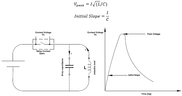
As the voltage Vc across the contact increases, an arc can strike between the contacts. Arcing will temporarily lower the contact voltage, but if the inductive energy is not fully dissipated then this energy will continue to flow into the stray capacitance and charge it again. At some voltage the arc will strike again, and stray capacitance is again discharged. This process can repeat itself multiple times until the inductive energy is completely dissipated or the contact has gained enough air gap dielectric strength to withstand the voltage. Remember the contacts are parting and is constantly gaining more and more air gap dielectric strength.
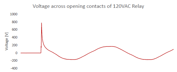
Figure 2 shows inductive ‘kick’ voltage when a 120VAC ice cube relay coil is deenergized. Note that regenerated voltage is ~800V peak for a 120VAC circuit! This high voltage can lead to contact arcing and eventual contact damage.
Arcing can also create potential electromagnetic compatibility issues as these transients can conduct through cables or radiate.
Contact Breakdown types
Contact breakdown can be due to Glow discharge or Arcing discharge.
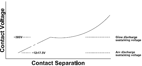
Glow Discharge: Glow discharge is a regenerative, self-supporting discharge or corona between two contacts when gas between contacts becomes ionized. This discharge is also known as ‘Townsend discharge’. For air at standard temperature and pressure ~320V is required at a gap of 0.0003inch to initiate glow discharge. If gap is shorter or longer then more voltage is required. After the contacts breakdown only a lesser voltage (~300V) is required to sustain the glow and this is independent of the contact gap.
A minimum current is required to sustain glow which is usually around few milliamps and is less than the current required to sustain arcing discharge (see below). To prevent glow discharge contact voltage needs to be kept below 300V.
Arc Discharge: Arc discharge occurs at lower voltage compare to glow discharge. Arc discharge is a function of contact material, is initiated due to field-initiated emissions and does not require presence of gas. High voltage gradient associated with contact opening initiates arc discharge. Once arc is initiated it can morph into metal-vapor arc. Presence of molten metal marks is an indication of the presence of metal-vapor arc. Once molten metal arc is formed, it forms a conductive bridge between contacts and could maintain the arc even if voltage gradient has fallen below the value necessary to initiate discharge. Metal vapor bridge is only limited by supply voltage and impedance of circuit. This conductive vapor bridge stretches and eventually ruptures. Metal vapor arc can lead to contact erosion or contact pitting leading to destruction of contact.
There is a minimum arcing voltage and minimum arcing current required to sustain the arc. If voltage or current is less than this value, then arc is extinguished. Table below shows the minimum arcing voltage and current for some common contact materials.

As you can see from the table it is very difficult to prevent initiation of arcing as the voltage required is low. Once arc is formed what we can do is to keep the available current (arcing current) below the minimum arcing current. Another method is to keep initial rate of rise of contact voltage below the value needed to produce arc discharge. A value of 1V/μs is satisfactory for most contacts.
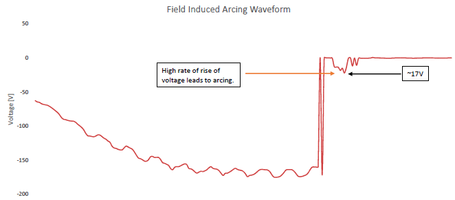
In figure 3 note that high rate of change of voltage causes arcing and arc voltage is limited to around ~17V which is a value determined by the type of material used for contact.
If stray capacitor is of large magnitude or if discrete capacitor is added in parallel with inductor, then it can lower the initial rate of rise of voltage and prevent arcing. However, adding discrete capacitors can cause contact damage on closing due to high current and hence is not usually recommended. An R-C snubber is a better choice.
Contact Arcing Waveform
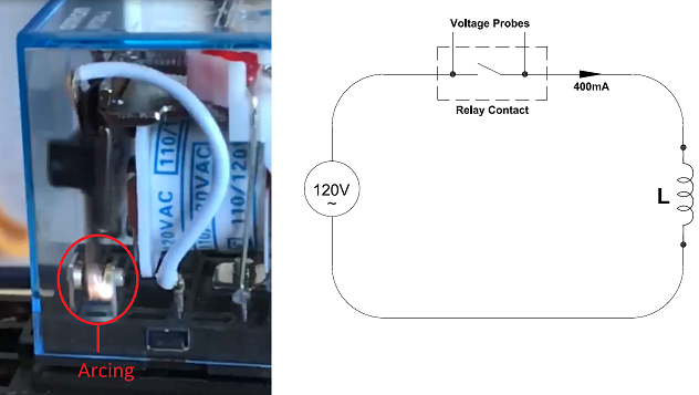
In this article relay contact arcing waveform is analyzed. An ice cube relay contact is made to interrupt 400mA of purely inductive current. Voltage across relay contacts is measured, see figure 5. Interrupting inductive current produces visible arcing inside the relay. For this test no surge suppression is used.
Waveform obtained across the contacts is shown in figure 6. Contacts are completely opened in 3.5ms.
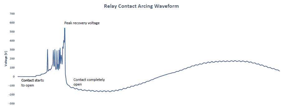
Referring to figure 6, initially when contacts are closed, voltage across contact is zero volts. As the contacts starts to separate the voltage initially increases linearly. If the rate of rise of voltage at this stage is high then field induced arcing can occur.
Expanded view of figure 6 is given in figure 7. Looking at the graph it is seen that the initial rate of rise of voltage is very less (~0.1V/μs) and arcing discharge does not occur. There is no evidence of arcing in the initial phase. When natural voltage of the sine wave approaches zero (which means the inductive current is at its peak), the opening contact experiences first inductive transient voltage spike. When this voltage reaches ~320V first glow discharge occurs which will discharge the charge accumulated in stray capacitance (see figure 1). Glow discharge is the reason voltage is limited to ~300V. First glow discharge is followed by more glow discharges. Lack of continuous discharge indicates inductor is not capable of supplying enough current to sustain a continuous glow discharge. At some point the inductor is not able to supply enough current to sustain the glow and no more glow discharge occurs. Inductor continues to dump charge in to stray capacitance and voltage rises to the peak recovery voltage after which there is no more energy stored in inductor and the contact has gained full dielectric strength. This completes contact separation process.
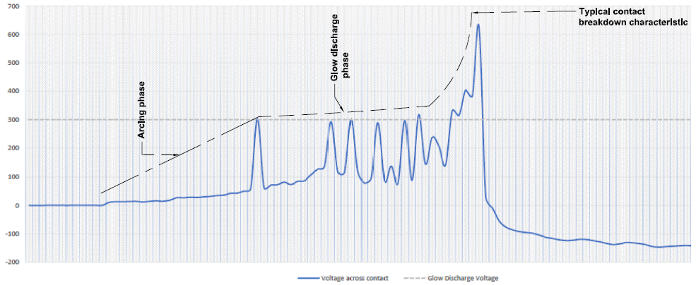
In figure 7, it can be observed that each discharge is limited to ~300V which is a tell-tale sign of glow discharge.
Methods available to prevent contact arcing
To prevent contact arcing, one of the contact arc suppression methods needs to be used. Some common methods are:
- Diode
- Resistor-Capacitor [Snubber]
- Resistor-Capacitor-Diode [R-C-D]
- Back to Back Zener Diode
- Metal Oxide Varistor [MOV]
Of these Diode and R-C-D methods can only be used with DC circuits.
Summary
- Contact arcing occurs when inductive loads are disconnected.
- Voltage developed across contacts can be many times the nominal voltage.
- High voltage can lead to contact arcing and eventual contact destruction.
- Contact arcing can be due to: Arcing discharge or Glow discharge
- Arcing discharge is a field induced emission occurring due to high rate of rise of voltage.
- Arc discharge is a function of contact material.
- Arcing discharge can cause localized metal vapor which result in metal vapor arc.
- Arcing discharge is a low voltage high current phenomenon.
- To prevent arcing discharge, keep initial rate of rise of voltage to 1V/μs or below or limit the available current below minimum arcing current.
- Presence of molten metal chunk on contacts is a sign of metal vapor arc.
- Glow discharge is regenerative discharge when gas between contacts become ionized.
- Glow discharge is a high voltage low current phenomenon.
- To prevent glow discharge, keep contact voltage below 300V.
- Use one of the surge suppression techniques to prevent contact arcing.
