Duplex Reactor or Duplex Current Limiting Reactor consists of two otherwise single-phase reactors physically arranged such that their magnetic fields are interlinked in an opposing fashion. The normal working current in one phase partially erases the voltage drop in the other winding. With balanced loading the reactive loss and voltage drop will be lower than that of two independent reactors. This is because under balanced loading, magnetic flux produced by each coil is in opposition while during a short circuit condition on one side the magnetic flux is additive thereby increasing the impedance and hence reducing the fault current. Duplex reactors can be used in situations where a large power source is split in to two buses that are similarly loaded. Under normal balanced load circumstances, the reactance of the two branches will be low. Under fault conditions on one side of the reactor a higher reactance results which limit the short circuit fault current. This is the basic operation of the Duplex reactor in simple terms. Duplex reactors are not very common in modern power system design though it has attractive properties. Most of the modern designs to limit short circuit current involve using air core current limiting reactors.
Schematic of duplex reactor is shown below.
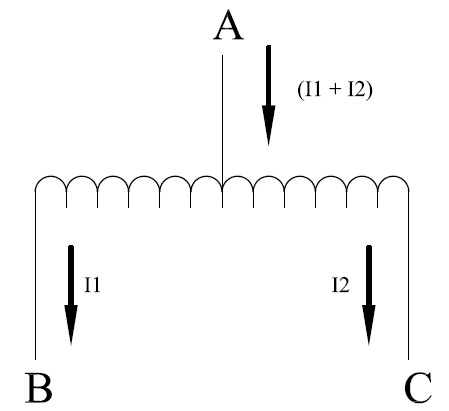
Duplex Reactor
When only one branch of the duplex reactor carries current, the circuit behaves like a single phase current limiting reactor. Coupling factor fc determines the amount of magnetic flux linkage between windings 1 & 2. Ideal coupling factor of 1 cannot be achieved, more practical values are close to 0.5. In the above figure, B and C are the load buses while A is the source bus. By using duplex reactor as shown above, short circuit limitation is achieved at either B or C.
Equivalent Circuit of Duplex Reactor
Flow of current I in coil1 results in reactive voltage drop of IX and will induce a voltage of IXfc in coil2 in the opposing sense. The equations expressing these relationships are below:
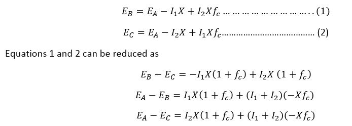
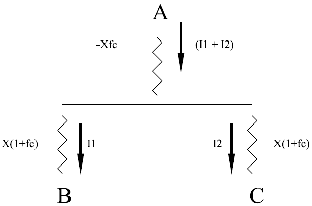
The equivalent circuit of the duplex reactor that satisfies these equations is shown in figure below. X represents the reactance of one half of the duplex reactor.

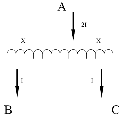
Duplex Reactor Equivalent Circuit
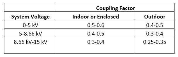
Typical values of coupling coefficient are provided in the table below.
Duplex Reactor: Losses and Voltage Drop
Consider a situation where equal currents I flow in each half of the duplex reactor to give a total current of 2I in the common circuit.
Reactive loss for each branch is I2X to give a total loss of 2I2X for the duplex reactor. Total reactive power loss for duplex reactor can be calculated as follows:
Total reactive loss= Branch A +Branch B +Branch C
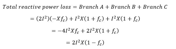
It can be seen from the equation for the reactive power loss above that the loss is reduced with better coupling coefficient. With zero coupling coefficient the losses are identical to that of two independent reactors. With ideal coupling coefficient of 1 the reactive loss will be zero. A more practical value of coupling coefficient is 0.5 which results in reactive loss that is half the value of two independent reactors.
Magnetic coupling coefficient fc only determines the reactive losses. The resistive power loss do not dependent of fc and is stays constant for a given value of load current.
Duplex Reactor: Voltage Drop
Reactive voltage drop from A to B is given by:
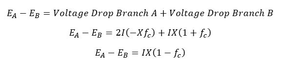
Under no coupling condition (fc=0), the reactive voltage drop is IX which is same as with independent reactors. Under balanced current load with equal currents in both branches of Duplex Reactor, the reactive voltage drop varies in direct proportion to coupling coefficient fc.
Duplex Reactor Under Short Circuit Condition
When a short circuit occurs on one side of the duplex coil, the full reactance of that coil X is available to limit the short circuit current. Thus, full reactive voltage drop is available during short circuit whereas voltage drop is partially erased during normal load applications. It is this valuable property that makes Duplex Reactor a unique short circuit current limiting device.
Possible Over voltage Condition in Duplex Reactor
Engineers using the Duplex reactor must be mindful of the possible voltage rise on the unfaulted end of the reactor. It is often desirable to limit the voltage rise to 110% normal on unfaulted terminal.
The absence of a positive external reactance in the common terminal (A) would leave a net negative reactance in this branch. In this case, the current to a short circuit on B in passing through -Xfc in branch A would create a severe voltage rise on the reactor C terminal/ This could inflict damage to the connected apparatus.
To avoid this, the positive sequence reactance of the power system to which the duplex reactor is connected need to be equal to -Xfc. This will help prevent excessive voltage rise on the unfaulted branch during a short circuit.
Additional Reading:
Current Limiting Sizing Calculation
Reference: ‘Duplex Reactor’, Industrial Power System Data Book, General Electric Co, Dec 4, 1961.