Broken delta refers to the connection of Voltage Transformers (VT) or Potential Transformers (PT) in a series fashion to calculate the zero-sequence voltage of the system. Three VTs are required for this connection. This connection is primarily used in ground fault detection of ungrounded systems.
When a ground fault occurs in an ungrounded system, the fault current will be close to zero making it difficult to locate and isolate ground fault using traditional ground overcurrent relay. A parameter that can be used to our advantage in the detection and isolation of ground fault on ungrounded system is the zero-sequence voltage during ground fault.
When a single line to ground fault occurs on ungrounded system, the faulted phase voltage will collapse to zero while the other two phases remain healthy. From sequence components theory, we know that when we add the three phase voltages, we get three times the zero-sequence voltage (V0) as shown below. This is sometimes also referred to as 3V0 protection though the term is not very common.
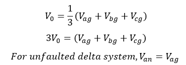
When there is a ground fault on A phase, the Vag voltage will be zero. However, Vbg and Vcg voltage rise from normal line to ground voltage to line to line voltage. This can be seen in the vector diagram below.
Also note that the Vbg and Vcg phase angles change from normal 1200 to 1500 , a 300 degree change when ‘a’ phase is faulted to ground.
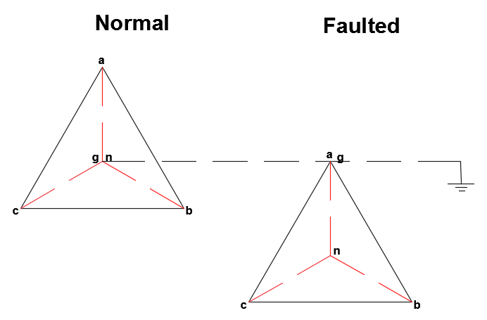
Ground fault on ungrounded system
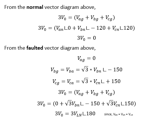
The voltage available at the secondary of the broken delta VT will be hence 3 times the rated line-neutral voltage when a single line to ground fault occurs in an ungrounded system.
A method to get 3V0 is to add the three phase voltages vectorially by connecting three VTs in series. The ends of the VT are not ‘joined’ and hence the term broken delta. Note that this is different from open delta which uses only two transformers and is used for different purposes but not ground fault detection.
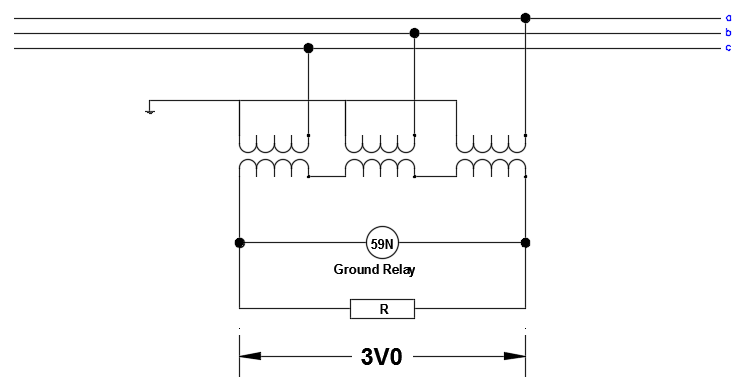
Broken delta ground fault detection
The three VT connected are connected in series as shown above. The voltage at both the ends of the connection is 3V0 (see equation for zero sequence voltage above). Under normally operating condition (unfaulted condition), the voltage across the three VT will sum to zero. When a single line to ground fault occurs, the voltage across the VT will be 3V0 and this can be used for ground fault detection. The ground fault relay element (59N) is connected across the open end of the series connected VT and need to be set below 3pu for effective detection of ground fault.
A resistor (called ballast resistor) is used to load the VT secondary as shown in the figure above. This is done for two purposes:
-
Stabilize the VT secondary voltage.
-
Prevent ferroresonance between VT and system capacitance.
Broken Delta Transformer Design Considerations
-
Use Line-Line rated VT: Under a fault condition, each VT is exposed to 1.73 times the nominal phase-ground voltage even though they are connected line to ground. This is due to shifting of the ‘neutral’ position of delta voltage triangle during a single line to ground fault. The individual VT should be rated for line-line voltage.
-
Use Loading resistor: Since broken delta connection is used typically in ungrounded systems, the configuration has a tendency to drift in to ferroresonance. If you notice the circuit diagram for broken delta connection, the primary VT circuit is wye grounded. This configuration makes it vulnerable to damaging ferroresonant oscillations between VT magnetizing reactance and system stray capacitance. The easy way to prevent this is to load the VT secondary with a loading resistor (ballast resistor). The resistor is sized anywhere from 30-50% of the VA rating of the voltage transformer.
Broken Delta ground fault detection on grounded systems
Commonly, broken delta is used for ground fault detection on ungrounded system. Use of this scheme for ground fault detection on grounded wye systems are not common since other sensitive methods of ground detection using current transformers (CT) and ground overcurrent relays are readily available.
Broken delta scheme can however be used on grounded wye systems. See the vector position below for normal condition and when a ground fault occurs on ‘A’ phase.
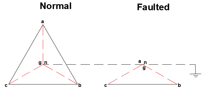
Ground fault on grounded system
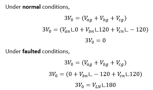
This indicates that when broken delta is applied in grounded systems we get normal line to neutral voltage across the windings unlike when applied on ungrounded systems which provide 3 times the line to neutral voltage.
Here is the summary of the broken delta output voltage for various grounding conditions:

If there is a system that can become alternatively grounded and ungrounded depending on the source connection, then the ground fault 59N relay can be set to lower than VLN for ground detection in both cases when broken delta is used. Broken delta can also detect double line to ground fault if the relay is set sensitively. An engineering review will be needed to arrive at suitable relay settings.
Broken Delta vs Open Delta
Broken Delta
-
Primarily used for ground detection on ungrounded systems
-
Uses three Voltage Transformers connected in series
-
Used to gather zero sequence voltage for ground fault detection and other relaying applications
-
Needs line-line rated VT for ground fault detection
-
Secondary circuit of broken delta needs to be loaded to prevent ferroresonance
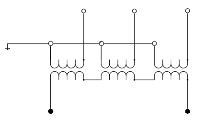
Broken delta connection
Open Delta
-
Open delta connection is primarily an economical way to provide three-phase power using only two single phase transformers.
-
Providing power using open delta connection is not very efficient
-
Open delta power transformer connection is prone to voltage unbalance issues
-
Requires larger kVA size transformers for a given load compared to regular three phase transformers
-
Open delta connection can be used for economical voltage metering application especially at medium voltage (>1kV).
-
For voltage metering using open delta connection, two VT provide all three line-line voltages.
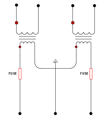
Open delta connection
