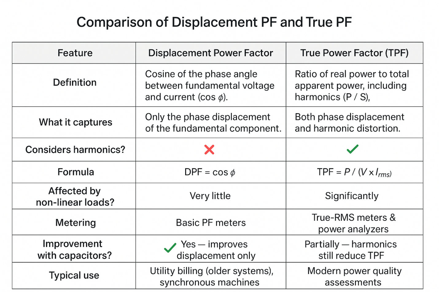
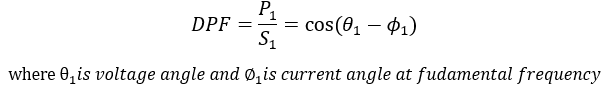
Displacement power factor [DPF] is the cosine of the angle difference between fundamental frequency voltage and current waveform. Harmonics are ignored in DPF calculation. DPF can also be calculated using ratio of fundamental frequency real (W) and apparent power (VA).
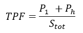
True power factor, also known as total power factor [TPF] is the ratio of true power (W) to apparent power (VA) after considering waveform distortion caused by the presence of harmonics. Both fundamental and harmonic frequency power are used in TPF calculation. In other words, distortion power due to harmonics is included in the calculation of TPF.

When there are no harmonic components present in the system, total or true power factor [TPF] will be equal to DPF. Under typical industrial conditions with a mix of linear and non-linear loads, TPF will be less than DPF.
Link to: Power Factor Calculator
Read: How to wire power factor controller?
DISCUSSION ON DPF AND TPF
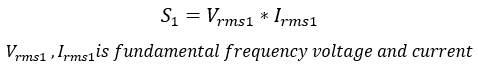
For sinusoidal waveforms, power factor is normally understood as the cosine of the angle between voltage and current. Using the same concept, and from power triangle, PF is also given by the ratio of real power (W) to apparent power (VA). Single phase apparent power S can be defined as following for sinusoidal condition:
However, in modern installations with non-linear load, the presence of harmonics means the presence of non-fundamental component (3rd, 5th harmonic etc.).
Read: Power factor improvement and transformer loading
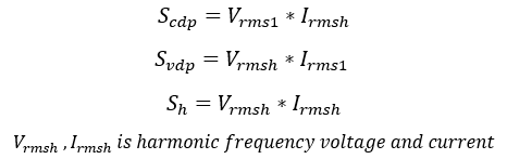
There are three terms relevant to this discussion: current distortion apparent power (Scdp), voltage distortion apparent power (Svdp) and harmonic apparent power (Sh).
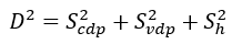
A term distortion power ‘D’ can be defined as:
Total apparent power S is then calculated as:
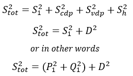
Apparent power Stot is thus the sum of fundamental frequency apparent power and distortion power D. Harmonic apparent power (Sh) can be written as:
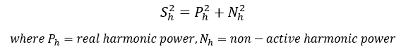
Looking at the above equation, harmonic apparent power is sum of real harmonic power and non-active harmonic power. Note that there is nothing like harmonic ‘reactive’ power.
Read: AC voltage drop and system power factor
DISPLACEMENT POWER FACTOR: For a sinusoidal waveform where P1 and S1 are the fundamental frequency real and apparent power respectively, displacement power factor (DPF) is defined as:
TRUE POWER FACTOR: For non-sinusoidal conditions, true power factor considers fundamental real power (P1), harmonic real power (Ph) and total apparent power (Stot). In other words, all the harmonic power demand of the load is used in this calculation and then divided by the total apparent power (Stot) consumed from the utility.
Apparent power ‘Stot’ is calculated using the sum of fundamental apparent power and distortion power ‘D’ as shown earlier in this article. Figure 2 shows an actual example with a linear load and non-linear load with different wattages. The values of angles and fundamental and harmonic powers were obtained from the power analyzer meter.
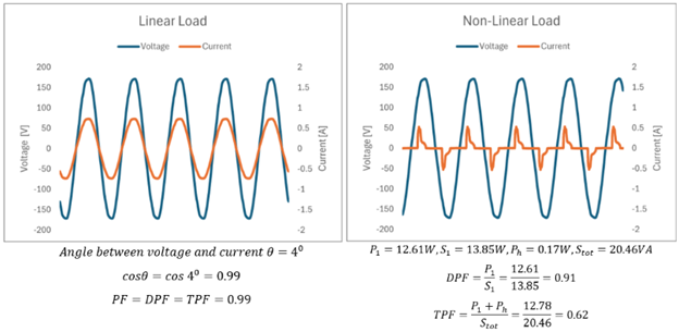
Figure 2 illustrates that for a linear load, PF calculation is straightforward. Cosine of angle or the ratio of real to apparent power, will give the DPF. Both DPF and TPF will be the same in the case of a linear load. For non-linear load, even when DPF may be relatively high (0.91 in this example), the total PF (TPF) can be much lower (0.62 in this example).
Read: Capacitor bank discharge methods
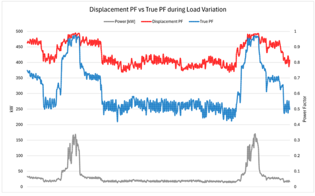
Figure 3 shows measurement data from an actual installation. Notice that during periods of low real load (kW), displacement PF [DPF] and true PF [TPF] differ by a great margin. During periods of larger real load (kW), DPF and TPF closely trend together. Why is this the case?
Period of low real load: During this period, majority of the remaining loads in the facility will be lighting (read LED lights, etc.). This means during periods of light demand, load is primarily non-linear load, and harmonic power (Ph) will be a larger percentage compared to fundamental frequency power (P1), causing TPF to be low.
Period of heavy real load: During this period, the real power demand (P1) will be much larger than harmonic power (Ph) causing DPF and TPF to more closely align. Notice that even during periods of heavy load, TPF is lower than DPF due to the presence of harmonics.
Read: Harmonic resonance in power systems

Devices such as LED lighting, computer power supplies have close to unity fundamental (50/60Hz) power factor. However, these devices also have terrible true or total PF often in the range of 0.5 to 0.6. Installing PF correction capacitors will not correct poor TPF for such electronic loads. Note that harmonic apparent power (Sh) only has two components-real harmonic power and non-active harmonic power.
Harmonic apparent power can be written as:

There is nothing like ‘harmonic reactive power’ similar to ‘fundamental frequency reactive power’ Q1. A capacitor bank will not correct poor TPF of non-linear loads because there is no harmonic reactive power to compensate for. Take an example of an LED light- there is almost zero fundamental frequency reactive power demand (Q1) while LED will be still producing significant harmonic currents, causing low TPF. A traditional capacitor bank will only compensate for the fundamental frequency reactive power demand (Q1) of the load.