Power capacitors in 3 phase capacitor bank connections are either delta connected or star (wye) connected. Between the two types of connections, there are differences in their applications, kVAR rating, detection of failed capacitors etc. In this article the difference between star and delta connected capacitors and the advantage of star vs delta connected capacitor bank is discussed.
The calculator below can be used for calculating effective kVAR produced for capacitor in delta connection or in star connection.

High Voltage Capacitors
Delta Connected Capacitor Bank
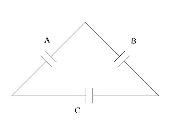
Delta connected capacitors are most commonly used at low voltage though it could be applied at higher voltages as well. Each capacitor will have the full phase-phase voltage applied across its terminal. Why low voltage capacitor banks are connected in delta? Remember that the kVAR generated varies as the square of applied voltage. The formula for VAR generated in a capacitor bank is given by:

Connecting the capacitor bank in delta produces more VAR compared to connecting in star. This is because in star connection only line-neutral voltage is applied across capacitor vs full phase-phase voltage is applied in the case of delta connection.

Delta connection of capacitors
Delta connection of capacitors requires two bushings. Since there is no connection to ground, the capacitor bank cannot be a ‘sink’ for any ground currents or zero sequence currents. Individual branch of the delta connected capacitor need to be protected against phase-phase short circuit by a current limiting fuse.
Star Connected Capacitor Bank
In star connection, the voltage across each capacitor is 1/sqrt(3) times the phase-phase voltage. Hence the VAR produced also will be correspondingly smaller when compared to delta connection. Star connection is primarily used at medium voltage (>1 kV) systems. One of the main advantage of using star connection is that the capacitor need to be only rated for system phase-neutral voltage compared to phase-phase rated in a delta system. Individual medium voltage capacitors hence will only be stressed at a lower voltage level thereby increasing its life. There are also other advantages in using star connection at medium voltage capacitors. There are two main types of star connection:
Grounded Star (Wye)
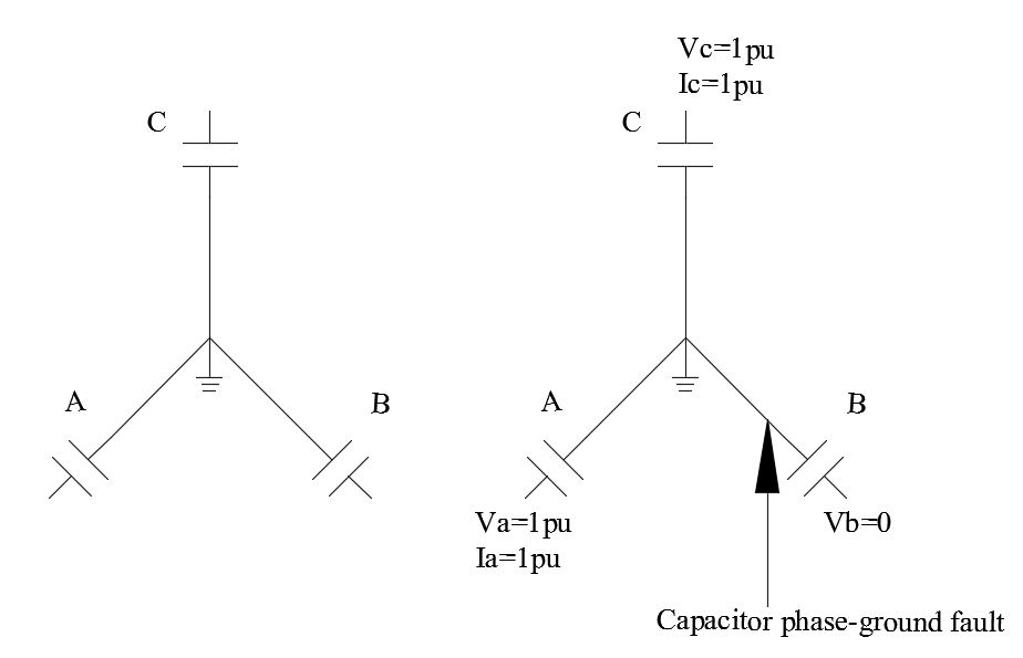
In a grounded star or grounded wye connection, the neutral point of the bank is solidly grounded (earthed). This means that the neutral need not be insulated to the full system BIL level. Hence, some saving in cost can be realized by using this connection. Additionally, transient recovery voltage (TRV) may be less severe in this connection. A fault on one phase of the capacitor bank will not result in any voltage rise in the other healthy legs of the bank. As shown below a fault on B phase capacitor will not result in voltage rise on the other healthy phases.

Star grounded connection of capacitor
Disadvantage of the grounded wye connection is that the grounded neutral can carry ground currents and zero sequence harmonic currents. These could cause telephone interference. Additionally, the grounded wye bank will also contribute fault current in the system during a phase-ground fault. Due to grounded connection high phase-ground current can flow when a capacitor fails to ground. This necessitates the use of current limiting fuses for this application.
Ungrounded Star (Wye)
In ungrounded star connection, the neutral point of the capacitor bank is not connected to ground. Hence this connection does not permit the flow of ground currents and zero sequence harmonic currents. For a system phase-ground fault the ungrounded wye bank will not contribute any fault current.
Disadvantage of this connection is that the bank neutral needs to be fully insulated to system phase-phase voltage. The neutral point could be at the phase-phase potential during switching action or during a fault condition. For banks above 15kV this could get expensive.
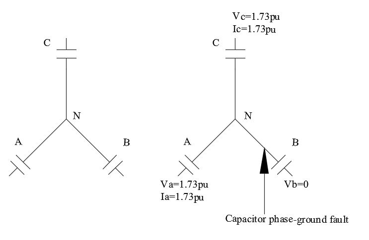
Another disadvantage of this connection is that when capacitor on one phase fails, neutral point is shifted. The voltage across the unfaulted (healthy phases) will rise to full phase-phase potential. Current through the unfaulted capacitors reaches 1.732pu and the maximum current on the faulted phase will be 3pu. Such increase in voltage and current in the bank could lead to additional failures.
As shown below a fault on B phase capacitor will result in voltage rise of 1.732 (sqrt of 3) times the nominal line to neutral voltage which is the full phase-phase voltage on the other healthy phases. The healthy capacitors hence will be over stressed and the protective relaying will have to quickly clear the fault to prevent damage to the healthy capacitors.

Star ungrounded connection of capacitor
There are other variations of this connection like ungrounded split wye and grounded split wye.
Additional Reading:
