Introduction:
Some of the frequent and troublesome VFD faults are related to the DC bus voltage. The VFD control circuit continuously monitor the magnitude and quality of DC bus voltage (DC link voltage or reservoir voltage) and triggers appropriate protective functions when the thresholds are crossed.
Some important protective functions derived from DC bus voltage are:
- Under voltage
- Over voltage
- DC bus ripple
Oftentimes when a drive trips on under voltage or over voltage, it becomes necessary to measure the DC bus voltage. Many drives can display real time DC bus voltage on the HMI screen. However, if it is desired to do data logging of the DC voltage or if it is suspected that the DC voltage sensing circuit is malfunctioning, then it may be required to measure DC bus voltage. A malfunctioning DC voltage sensing circuitry can lead to nuisance under or over voltage trip. The magnitude at which under voltage and over voltage trip is triggered varies between manufacturers and it is best to contact the manufacturer about the actual voltage at which trip happens. The table below summarizes the under voltage and over voltage trip settings for few VFD manufacturers.
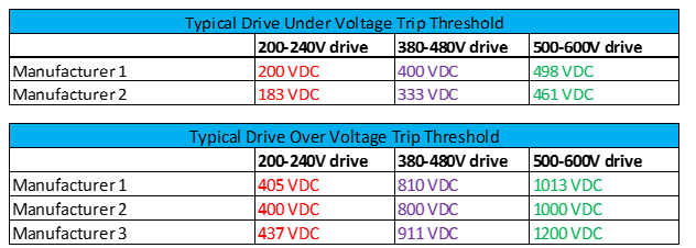
Typical VFD Undervoltage and Overvoltage Fault Thresholds
Measuring DC Bus Voltage
Here are the few considerations before attempting to measure DC bus Voltage:
- Safety
- Selecting Right Equipment
- Knowledge on how to capture the relevant information
1. Safety:
DC bus voltage in a drive will be much higher than the AC RMS input voltage. This should be kept in mind while attempting to measure the DC voltage. Here are the nominal values of DC bus voltage. Account for up to 5-10% increase in voltage due to higher AC input voltage from these values. The test equipment and accessories selected for the application must be rated above these DC voltages.
- 230V System: 310 VDC
- 415V System: 560 VDC
- 480V System: 648 VDC
- 600V System: 810 VDC
Capacitor Voltage: Before attempting to connect to the DC bus voltage, de energize the drive and wait for 3-5 minutes to allow complete discharge of stored energy in the capacitors.
2. Selecting Right Equipment:
Real time DC bus voltage can be measured using appropriately rated multimeter or a handheld battery powered oscilloscope.
Before using any kind of measurement device on the DC bus, the following should be noted. Refer drive schematic below.
- Neither end of the DC bus capacitor [DC+ or DC-] is at ground potential.
- For medium to large drives, there will be two capacitors in series with the center point grounded.
Many bench type oscilloscopes have the probe ground clip and the AC input ground connected. This is done for safety reasons. However, when we try to put one of the grounded probe clips on to DC+ or DC-, the capacitor will be short circuited and a tremendous fault can flow from the capacitor back to the AC service panels ground through the test equipment. This could damage or destroy the test equipment.
Hence It is preferred that a handheld battery powered oscilloscope is used instead of a bench type oscilloscope. Handheld oscilloscopes have no reference to AC system ground and hence are not susceptible to ground current flow.
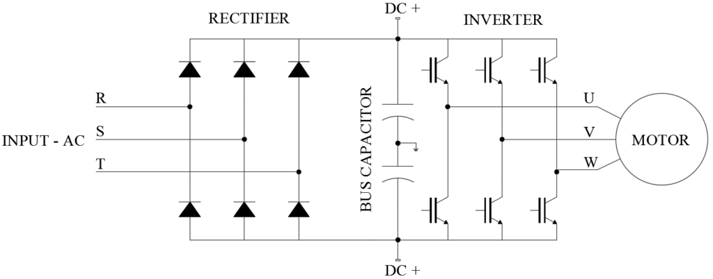
Drive Schematic Showing DC Bus Capacitor and Center Point Ground of Capacitors
An example of handheld oscilloscope is Fluke 190 or 43B series.
Another good idea is to use 10x probes while working with DC bus measurements. 10x oscilloscope probe scales down the voltage by a factor of 10 before it gets to the oscilloscope. When working with a 480V drive with DC bus voltage of 678 VDC, the 10x probe effectively will only have 67.8 VDC at the oscilloscope end of the cable. The scale factor in the oscilloscope will have to be adjusted for the 10x probe.
An example of 10x probe is Fluke VPS40. Select properly voltage rated probes for the application.
Use the oscilloscope, test accessories etc. that are rated for the expected DC voltage for the application.
3. Knowledge on how to capture the relevant information
Measuring DC Bus Voltage
Before measuring the DC bus potential, manufacturer data sheet will have to be reviewed to find out where are the test terminals are for that model of drive.
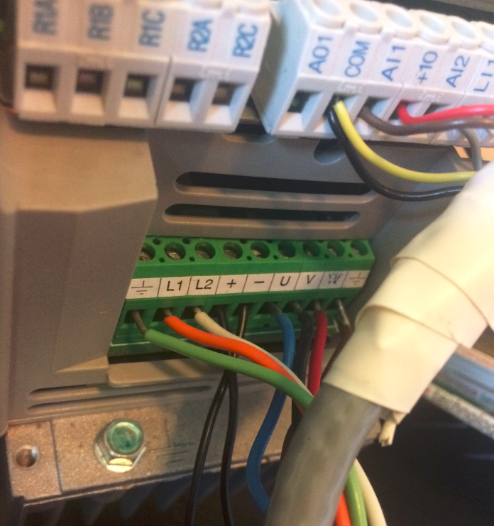
Measuring DC Bus Voltage on VFD. Notice the test point identified as + and –
AC Coupled or DC Coupled?
To measure the steady state DC voltage, use DC coupled. Use AC coupled for ripple voltage measurement (see below).
Below is the DC bus voltage trend for a 75HP drive over a period of 3 days. The plot shows three instances of momentary AC input power loss and DC bus under voltage.
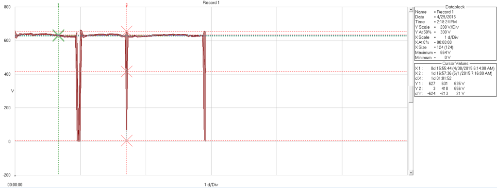
DC bus voltage trend for a 75HP drive
Performing steady state DC bus data logging can be helpful if the drive is experiencing nuisance over or under voltage fault. Data collected from this survey can be analyzed to identify the root cause behind DC bus voltage related faults.
For monitoring DC bus voltage for an extended duration, the sag/swell feature of oscilloscope can be used-if available. For Fluke 43B, sag/swell data is recorded every half cycle (around 8ms for 60Hz systems). By using this setting, the scope will record every half cycle of maximum, minimum and average DC bus voltage.
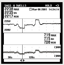
Using sag and swell feature to capture DC bus voltage
Measuring DC Bus Ripple Voltage
For measuring DC bus voltage ripple, select ‘AC Coupling’ on the oscilloscope. Adjust the time scale to between 2-10ms and the voltage scale to around 1V per division to properly visualize DC ripple. Measure the peak to peak voltage of the waveform to calculate the DC ripple voltage.
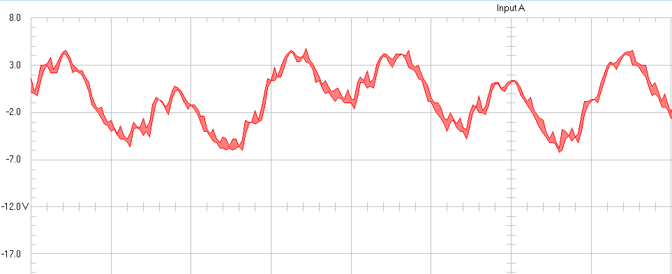
DC bus voltage ripple for fully loaded three phase drive
Note the small difference of around 1V in the DC ripple ‘peaks’ in the figure above is due to small difference in the AC system impedance between different phases. This is usually not a problem and could be caused by difference in line impedance due to transformer, cable, cable installation or even the impedance difference between phases in the electric utility grid. If the peaks voltage differs by large voltage (30-40V) then this could be an indication of some problem. See below.
DC ripple is typically between 5V and 10V for a healthy drive. If the ripple voltage is greater than 30-40V, then one of the possibilities below exists:
- One of the input diodes of the drive failed.
- One AC input phase lost.
- Severe unbalance on the AC input voltage.
- Severe impedance unbalance on the AC input line.
- DC bus capacitor is failing.
- Drive is undersized for the application.
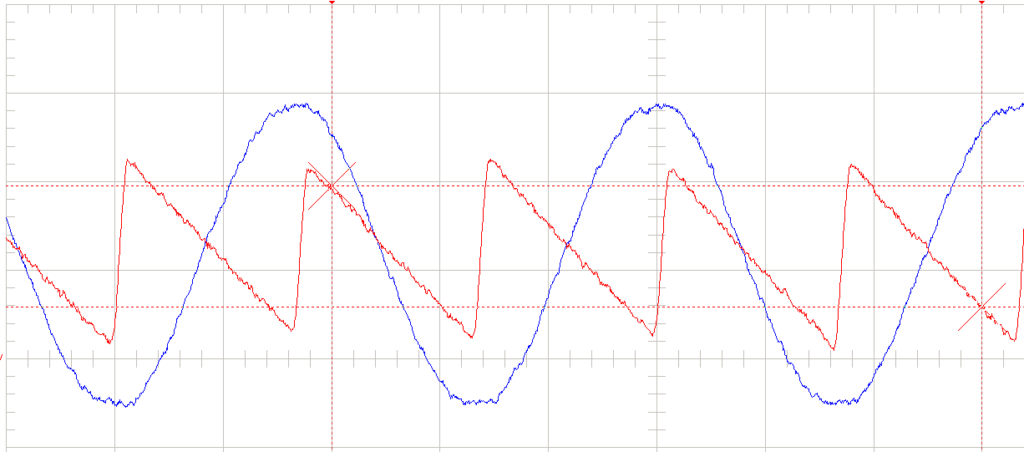
AC input voltage and DC bus voltage ripple for lightly loaded single phase drive
The figure above shows the AC input voltage and the DC bus voltage ripple for a single-phase drive that is lightly loaded. Notice that at each AC voltage ‘peak’, the capacitor charges to full voltage and then the voltage ramps down (due to the stored energy being used to run the motor). Capacitor again charges at the negative AC voltage ‘peak’ and the process repeats.
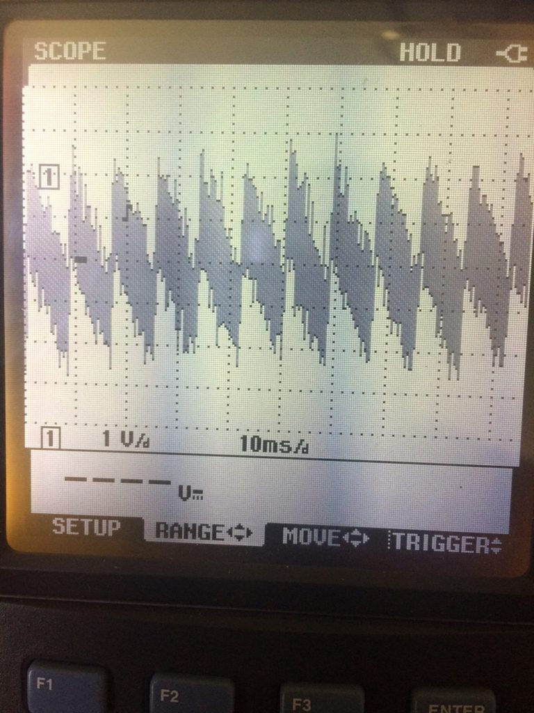
DC Voltage Ripple-As seen on oscilloscope
Note: The magnitude of DC ripple voltage depends on the load current of the drive and the size of the DC bus capacitor. Hence, comparison of ripple voltage between drives of different manufacturers or different horse power drives is not a correct comparison.
Conclusion: Measuring steady state DC bus voltage and DC ripple helps in troubleshooting drive over voltage or under voltage faults. By looking at the ripple voltage waveform important conclusions regarding the health of the drive and the AC input voltage can be made. DC bus voltage is considerable higher than AC input voltage and knowledge about selecting the right equipment and selecting the right test points is important. Do not perform these tests if you are not knowledgeable in any of these.
Also read: VFD overvoltage fault troubleshooting