DC power supplies may be connected in series, parallel or redundant configuration depending on the application need. When higher voltage output than that can be supplied by a single source is needed, sources can be connected in series. When higher current load or load sharing is needed then power supplies may be connected in parallel configuration. In critical applications that need power supply redundancy, redundant connected power supplies can be used.
DC POWER SUPPLIES IN SERIES
Series connection of power supplies may be used when higher output voltage is desired than that can be obtained from one power supply. Power supplies that are connected in series need to be of similar characteristics and preferably of same manufacturer and same model number. Power rating of the series connected circuit will be double that of a single power supply though the current that can be supplied will be limited by the individual power supply current capacity.
As an example, connecting two 24V, 2A, 48W power supplies in series will give a combined unit of 48V, 2A, 96W. Since the circuit is connected in series, current capacity is limited by the individual power supply (2A) though net power output is doubled.
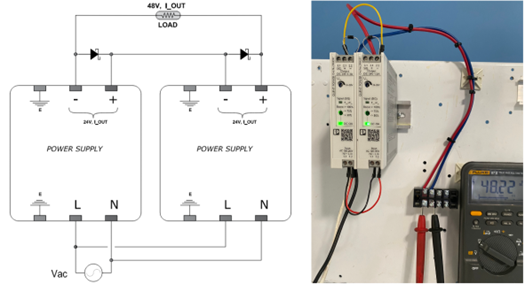
Multiple power supplies can be connected in series though higher voltages will exceed SELV requirements and additional protections may need to be installed. Reverse biased Schottky diodes need to be connected across the output terminals of each power supply to avoid power supply damage in the event of a load short circuit. Figure 1 shows two 24VDC power supplies connected in series to obtain 48VDC. Note the reverse biased Schottky diodes across each power supply.
Schottky diode need to have the following minimum characteristics:
- Reverse voltage rating of 2X output load voltage. For example, if the load voltage is 48VDC, the diode needs to have 96VDC reverse voltage rating.
- Current rating of 2X of rated load current.
Read: Power quality check using multimeter
DC POWER SUPPLIES IN PARALLEL
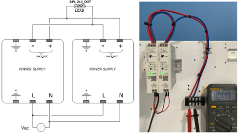
DC power supplies may be connected in parallel for either increased power output or improved redundancy. When connected in parallel, output current will be 2X of that of one individual power supply. Prior to connecting power supplies in parallel, output voltage of each unit must be checked to make sure their voltage difference is less than 25mV at 50% rated load current. It is preferred that both power supplies are of same type and part number.
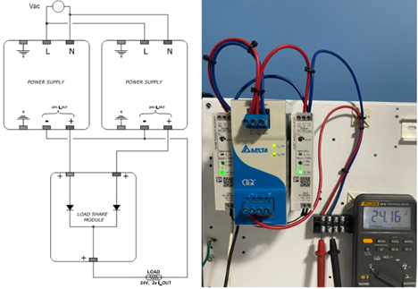
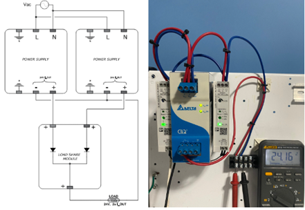
To provide protection against power supply short circuit, it is recommended to connect external diodes (ORing Diodes or Load share modules) when multiple power supplies are connected in parallel. See figure 3. With OR diodes, an output short circuit on one of the power supplies will not cause the other power supply to be short circuited. Diode will prevent any reverse current flow in to the failed power supply.
To achieve optimum performance when using current sharing, the following steps must be carried out:
- At 50% load measure individual power supply output DC voltage.
- At 50% load, adjust the output voltage of both power supplies to same value or within +/-25mV tolerance.
- Connect the two power supplies in parallel either using figure 2 or through load share module (OR Diodes) as in figure 3.
Read: What happens when phase and neutral are reversed?
DC POWER SUPPLIES IN REDUNDANT CONFIGURATION
Power supplies are often connected in parallel for redundancy purpose meaning failure of one of the power supplies should not affect the load voltage. In redundantly connected application, though the power supplies are connected in parallel, the net output current will be the same as that of one power supply and not 2X as that for load sharing arrangement. This is because one of the power supplies will be always in ‘standby’ mode and does not supply load current. Only the primary power supply will supply load current at all times and standby unit will only take over when primary power supply fails. Power supplies are connected using diode-based passive redundancy modules with some manufactures also offering active redundancy modules.
Before connecting the power supplies in redundant configuration, the output voltage of two power supplies should be measured and set with a difference of atleast 2% of rated voltage. For 24VDC power supplies, the difference voltage of two supplies must be atleast 0.48V or slightly above that (0.48V-0.5V). Voltage of the primary (preferred) source should be greater than that of standby (redundant) source by 0.48V-0.5V.
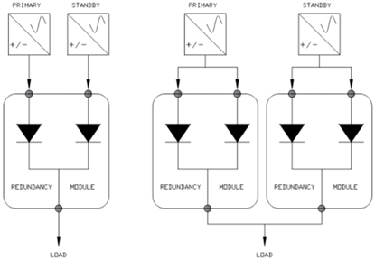
Two examples of redundant connections are shown in figure 5. First picture (on left) shows two power supplies that are connected in redundant fashion. If primary fails, standby power supply will take over. In the second picture on right, there is redundancy of power supplies as well as redundancy of redundancy modules.
To achieve optimum performance when connecting power supplies in redundant configuration, the following steps must be carried out:
- Designate one power supply as primary and another as standby.
- At 50% load measure individual power supply output DC voltage.
- At 50% load, adjust the output voltage of primary power supply to ~0.5V above that of standby power supply.
- Connect the two power supplies through redundancy module (OR Diodes) as in figure 3.
Under normal operating conditions, only the primary power supply will be supplying power to the load. In the event of preferred power supply failure, the standby (redundant) power supply will start supplying load current. Due to electronic diode-based switch over, there is no delay time in switching from primary to standby source.
When power supplies are connected in parallel for redundancy purposes, the current rating of a single power supply must meet the load current demand.