Poor power factor can cause large reactive current flow and increased kVA demand, which in turn could lead to utility penalties, voltage drop issues, etc. A factor not commonly understood is the real power (kW) loss in the system as a consequence of operating with poor power factor (PF). Poor power factor leads to increased real power loss requiring a larger generator power rating, a larger transformer, and an increased cross section of cables and conductors even though the actual load kW hasn’t changed. In addition, operating at a low power factor causes line voltage drop.
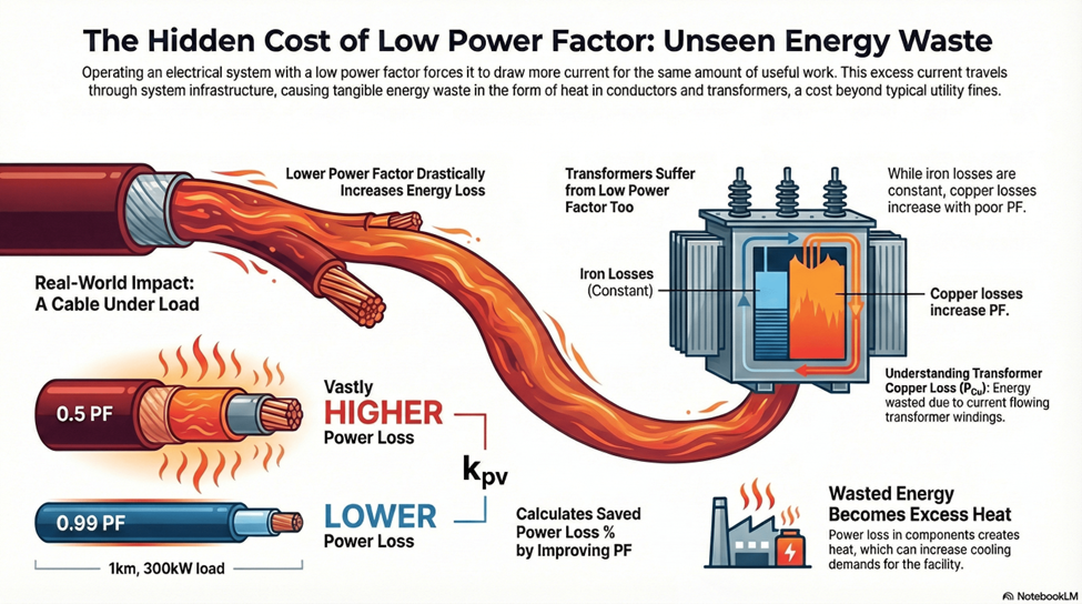
Real power loss is often not factored in while calculating return on investment for capacitor banks. Almost exclusively, priority is given to reducing the utility PF penalty, with the next priority being improving voltage regulation. Applying capacitor banks closer to end-use loads prevents reactive power from being circulated over large distances, thereby reducing power loss. Power loss on cables and transformers adds heat load, thus creating more facility cooling demand.
Read: Why is correcting PF to unity expensive?
In this article, the topic of real power (watts) loss due to operating at a low power factor is discussed. Primarily, low power factor causes power loss in cables and power transformers. The formula for calculating power losses at these locations are provided below.
Read: Displacement PF vs True PF
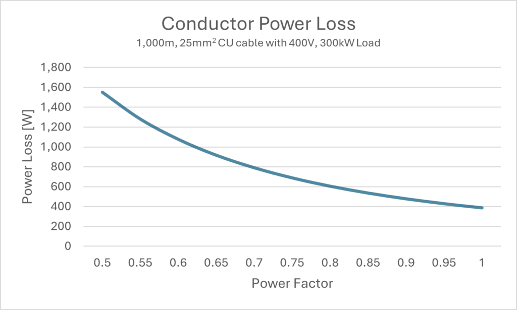
Conductor Power Loss
Low power factor leads to increased power loss in conductors. Losses increase quadratically with decreasing power factor.
The graph below shows conductor power loss on 25mm2 cross-section cable carrying 300 kW of load for a circuit length of 1000 m with PF varied between 0.5 and 0.99.
Link to: mm2 to AWG conversion
The power loss concept also illustrates why correcting PF ‘locally’ is more beneficial compared to a centralized PF correction. For a large facility, this means PF correction is ideally done at individual LV substations instead of at medium voltage (MV) substations.
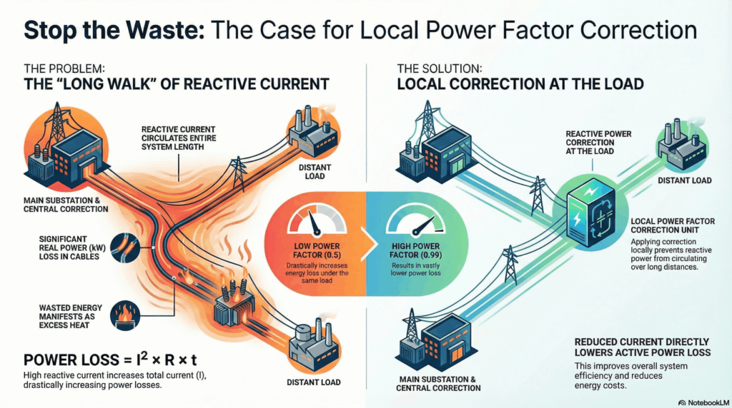
Installing PF correction at the MV substation means reactive current will have to flow through interconnecting cables, leading to power loss. Key design parameters to consider here are the circuit length, power transmitted, and load PF.
Improving fundamental frequency power factor will reduce the losses by the loss reduction factor (kpv):
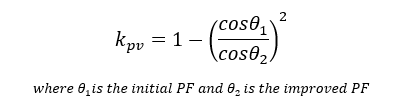
For example, improving PF from 0.65 to 0.95 will result in a 53% reduction in losses.
Transformer Power Loss
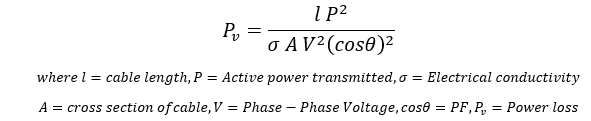
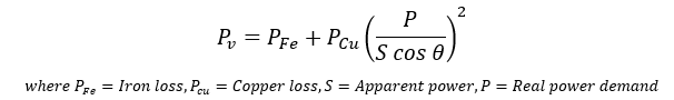
Similar to cables and conductors, operating with a poor power factor will cause additional real power loss in transformers too. There are two types of losses in a transformer: copper loss and iron loss. Iron loss is independent of PF, whereas copper losses depend on load current and PF. Total power loss (Pv) in the transformer is given by:
Read: Transformer current calculator
Summary
Operating loads with poor PF can lead to large reactive current flow.
Reactive (VAR) current flow over conductors can lead to real (W) power loss.
Power loss in conductors and transformers increases quadratically with decreasing PF.
It is beneficial to correct PF locally at the load to avoid reactive current flow over long distances.
Conductor power loss and energy loss due to poor PF can be calculated.
Conductor power loss is usually not paid attention while capacitor bank return on investment calculations are performed. It is prudent to do a conductor energy loss calculation if the circuit length is significant.
Operating a poor PF load also causes large real power loss in transformers that are part of the circuit.