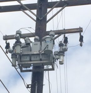
Reactive power is the power required by inductive devices (motors, transformers etc.) in power system to create magnetic field necessary for its operation. Magnetic field is very much necessary for the operation of these devices, however it does not contribute to useful work (watts).
The unit of reactive power is ‘vars’. Strictly speaking reactive power is not being ‘used’ it just circulates between the reactive power consumers (motors, transformers etc) and reactive power generators (capacitors etc.)
There are hundreds of articles written on the topic of reactive power and it is recommended that the reader refer to those articles if not familiar with reactive power. We will discuss how to measure reactive power.
How to Measure Reactive Power?
Most of us know the basics of reactive power, however many are not familiar with the various practical methods to measure reactive power. Below are some of the practical methods of measuring reactive power
-
Using a Power Meter
-
Using a Power Quality Meter
-
Straight display of reactive power using meter
-
Using wave form display
-
Using PF, KW
-
Using phasor
-
1. Using a Power Meter
This is straight forward. If the power meter has the capability to display reactive power, then the value can be read straight out of the meter. The power meter will need three phase (or single phase as the case may be) voltage and current input.
The CT polarity and wiring to the meter is very important as wrong CT/VT polarity will result in inaccurate results.
2. Using a Power Quality Meter
By using a power quality meter or a data logger we can calculate the reactive power delivered to the load. There are couple of ways to do this:
Meter Data:
Many meters will provide reactive power data if voltage and current channels are connected. Again, the CT polarity and having the correct current direction is important for accurate results.
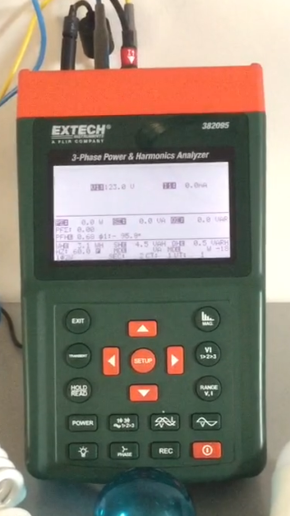
Power quality meter that can provide reactive power
From Waveform:
Reactive power can be calculated by calculating the phase angle difference between the voltage and current waveform. The easiest way to do this is to measure the time difference between the voltage positive peak and current positive peak as shown in the figure below.
Lagging Power Factor Waveform
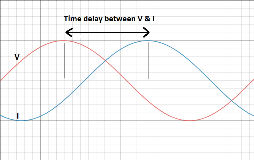
Voltage and current waveform with current (I) lagging voltage (V)
Leading Power Factor Waveform
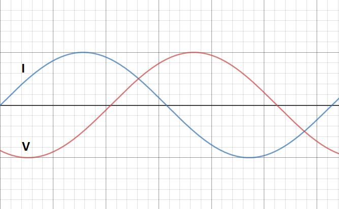
Voltage and current waveform with current (I) leading voltage (V)
Once the time difference is calculated (in milli seconds), use the following calculator to calculate the phase angle difference.
The calculator uses the following formula:
Where θ is the phase angle difference [Power Factor Angle] in degrees
f is the system frequency
Δt is the time delay between voltage and current waveform
Once the power factor angle is known, we need to know one additional parameter to calculate reactive power. That parameter could be KW or KVA.
Using Power Factor Angle (θ) & Kilo watt (KW) or KVA:
If power factor angle and the load KW is known, then the reactive power used by the load can be calculated using the reactive power formula below.

If power factor and the load KVA is known, then the reactive power used by the load can be calculated using the reactive power formula below.

Where θ is the power factor angle. Note that power factor is the cosine of power factor angle.
Using Phasors:
Phasor diagram showing voltage and current can be used to calculate the reactive power demand. From the phasor diagram, angle θ between voltage and current needs to be measured.
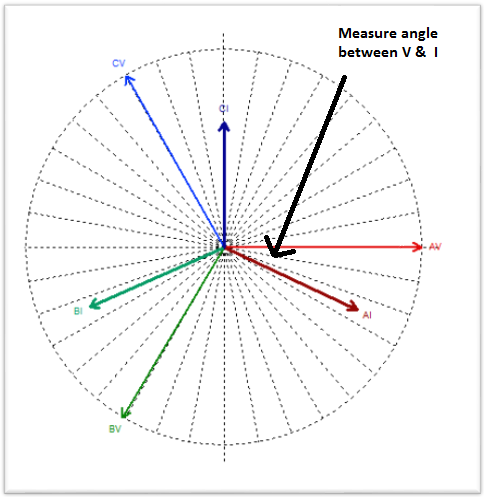
Using phasor diagram to measure reactive power
Once angle between voltage and current is known, then we need one additional data to calculate reactive power. The additional data could be KW or KVA.
If KW is known then reactive power (Kvar) can be calculated by:

If KVA is known then reactive power (Kvar) can be calculated by:


