Driving metallic earth rod in to ground is one of the basic steps in creating suitable earth or ground reference for an electrical installation. For a single electrode driven in to ground the equation for effective earth or ground resistance value is given by following equation:

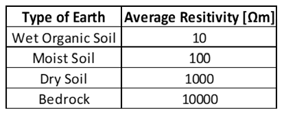
The following calculator can be used to calculate the earth or ground resistance for a single electrode driven in to ground. Typical soil resistivity values as provided in IEEE Std 80 is used or instead user can input soil resistivity data directly in to calculator. Note that conduction in soil is largely electrolytic. The amount of moisture and dissolved salts affects the resistivity of soil. Without actual measurement, accurate characterization of a particular soil as ‘wet organic soil’ or ‘moist soil’ is hard to define.

Measuring the actual soil resistivity can be accomplished by using the two common methods: Wenner method or Schlumberger method. If actual measurements are taken it is recommended to take readings at different locations to identify any anomalous readings. From the equation above, it can be seen that for earth resistance (Rg) to be low, the following parameters play role.
—
Soil Resistivity [ρ]: Low soil resistivity yields reduced earth resistance. The relationship between soil resistivity and effective electrode resistance is linear.
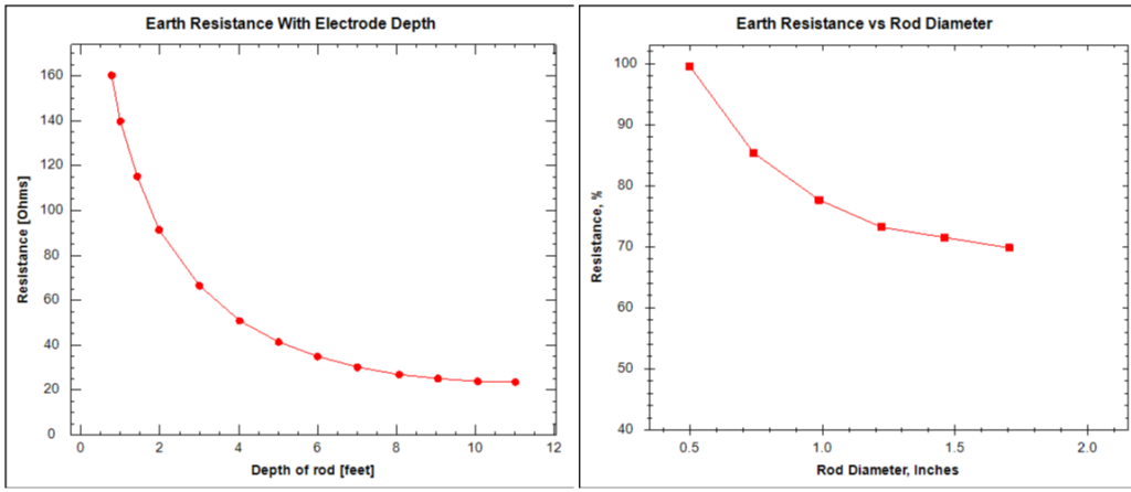
Length of Electrode [L]: Influence of electrode length on the earth resistance is not linear. All other parameters remaining the same, first few feet of electrode significantly reduce earth resistance but after around 8 feet it tends to flatten out.
Diameter of Electrode [d]: Increasing diameter of the electrode only has limited influence on earth resistance. Large diameter rods can be useful when driving in to hard terrain.

Other methods to reduce earth resistance include use of multiple rods in parallel or reduce the soil resistivity by chemical treatment.
Related Articles: Substation Grounding-Role of Crushed Rock
