![]()
Flow of DC current through a resistance result in voltage drop according to ohms law. For AC circuits, in addition to the voltage drop due to resistance of the conductors (IR), the flow of reactive power (Vars) causes additional voltage drop across the line inductive reactance (IX).
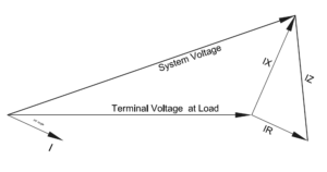
AC Voltage Drop Vectors
AC Voltage Drop Formula
The approximate formula for calculating the AC voltage drop from Line-Neutral is:
AC Voltage drop Line-Line is given by:
![]()
R= Resistance of feeder
X= Reactance of the feeder
I= Load Current
θ= Power factor angle of load current
The term RICos(θ) can be called the resistive voltage drop component and XISin(θ) can be called the reactive voltage drop component.
If you want to calculate the AC voltage drop use this calculator.
Two observations can be made from the voltage drop equation above.
1. Resistive voltage drop component is dependent on the product of resistance (R), current (I) and power factor (cos θ). Let’s see how the resistive voltage drop varies as the function of power factor for unit resistance and current.
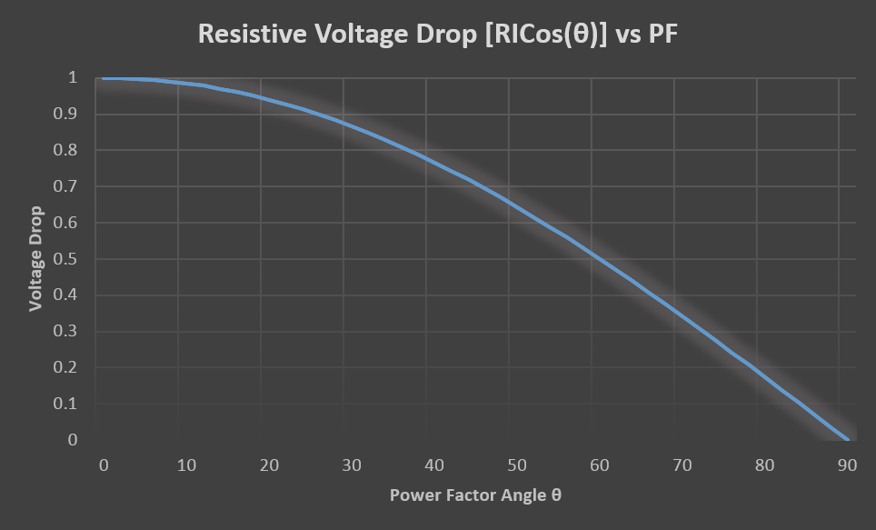
Resistive voltage drop vs power factor
As can be observed, resistive voltage drop is maximum at zero power factor angle and lowest at 90-degree power factor angle. Since ideal power factor angle is close to 0 degree, we can expect resistive component to dominate the voltage drop for loads with good high-power factor. For example, if the load is a resistive heater the power factor of the load will be unity and hence the power factor angle will be zero or very close to zero (θ ~ 0). From the voltage drop equation it can be calculated that the voltage drop line to neutral is:
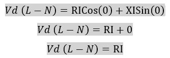
This indicates that the voltage drop across the conductor for a high power factor load (θ ~ 0) will be entirely resistive with zero reactive voltage drop.
2. Reactive voltage drop component is dependent on the product of reactance (X), current (I) and sine of the power factor angle (θ). Let’s see how the voltage drop varies as the function of power factor for unit resistance and current.
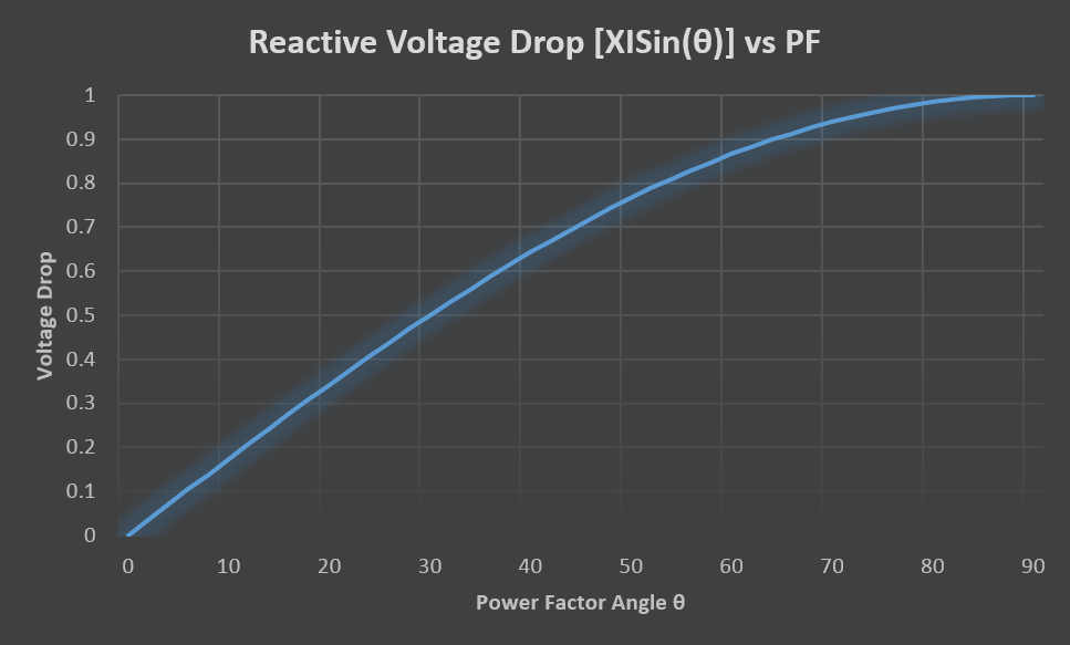
Reactive voltage drop vs power factor
Reactive voltage drop is minimum at zero power factor angle and maximum at 90-degree power factor angle. Since ideal power factor angle is close to 0 degree, we can expect reactive component to dominate the voltage drop in systems with poor power factor (θ ~900).
Both the reactive and resistive voltage drop components are combined in to one graph in the figure below.
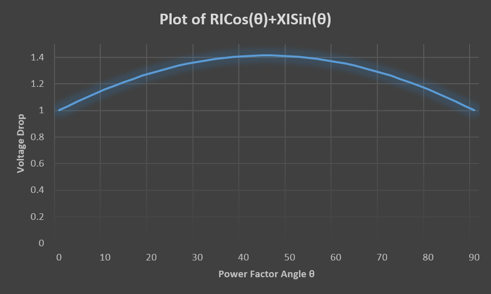
AC Voltage Drop Vs Power Factor
The plot of approximate AC voltage drop equation shows the variation of voltage drop when the load power factor is varied between θ=00 and θ=900 for unit value of R, X and load current. As can be observed the maximum value of voltage drop occurs for a power factor angle of 450 if the values of R and X are the same.
Practically speaking, for large power cables the value of inductive reactance will be 1-5 times the resistive component. In other words the X/R ratio will be high. For these circuits with high X/R ratio, the reactive component become much more prominent player in the overall voltage drop. Power transformers also have high X/R ratio between 5-15.
As an example, lets calculate the voltage drop across a 5kV cable 1000AWG with a length of 1000ft for a load current of 100A at power factor of 80% (θ=36.860). Published values of resistance and reactance over a distance of 1000ft is R=.0144Ω and X=.0361Ω.
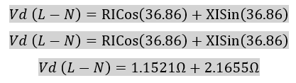
The resistive voltage drop is 1.1521Ω and the reactive voltage drop is 2.1655Ω or in other words the reactive voltage drop is 1.88 times the resistive voltage drop. Of course this value will change with load current and power factor.
If you want to calculate the AC voltage drop use this calculator.
Motor Starting
One of the main reason for the motor starting voltage drop in electric power system is due to the phenomenon discussed above. Motors under starting condition have very low power factor of around 0.2 and the inductive component in a motor dominates the X/R ratio. In other words, the X/R ratio of motor is large. Another contributing factor causing large starting voltage drop is the inrush current during startup. This could be 6-10 times the nominal full load current of the motor.
The combination of large current, poor power factor and high X/R ratio results in large voltage drop across the conductors in the system. Usually this results in temporary voltage sag until the motor reaches its synchronous speed. At synchronous speed the motor power factor improves to around 0.8-0.9 and the motor current will be the nominal load current based on the horse power of the motor.
How to mitigate voltage drop?
For a given value of load current and circuit length, voltage drop in AC power systems can be mitigated using the few techniques listed below:
-
Lower the circuit resistance: Use larger cross section area conductor or use multiple conductors in parallel.
-
Lower the circuit inductance: Use wire with lower inductance (usually thicker cables).
-
Reduce the current: Use step-up transformer to increase the voltage at source and hence lower the current that must be carried through the conductors. At the receiving end, a step-down transformer lowers the voltage to the desired value.
-
Improve the load power factor. Usually this is accomplished by the addition of power factor correction capacitors at the load terminals.