Motor Starting Current: Induction motor starting on full voltage (also known as across the line starting or direct on-line starting) has the undesirable effect of drawing five to ten times or more of motor full load current. Usually this starting current of induction motor persists till the motor reaches close to its synchronous speed (rated speed). Induction motors under starting conditions have extremely low power factor of around 10-30%. The combination of large starting current and poor power factor will cause large voltage drop across the system impedances. 3 phase motor inrush current calculator is provided in this article.
The large voltage drop created by induction motor starting can cause two major types of problems:
- The starting motor itself may not be able to accelerate to its rated full speed due to low bus voltage. Remember that starting torque of induction motor varies as square of the applied voltage.
- The voltage sag created by induction motor starting may cause lights to dim, contactors to drop out, variable frequency drives to shut down etc.
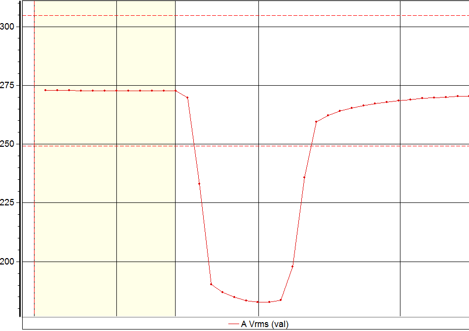
Voltage Sag – RMS
Induction Motor Electrical Equivalent Circuit
To understand why induction motor starting creates voltage sags and high starting current it is important to understand the equivalent circuit of an induction motor. The generic representation of induction motor equivalent circuit is provided in the figure below.
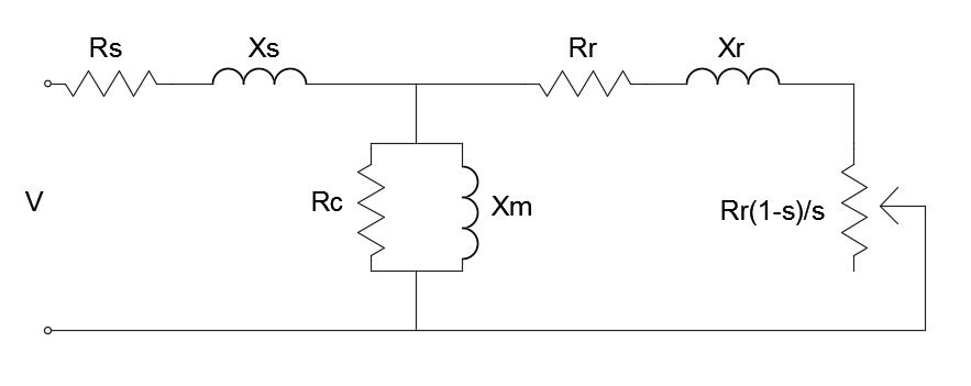
Induction Motor Model
The per-phase equivalent circuit of an induction motor under normal steady state condition is shown above. Here are the key impedances and resistances to understand:
Rs= Stator resistance Ω
Xs= Stator impedance Ω
Rc= Cores loss resistance Ω
Xm= magnetizing impedance Ω
Rr= Rotor resistance referred to the stator Ω
Xr= Rotor impedance referred to stator Ω
S= slip which is the ratio of the difference between the synchronous speed (ns) and rotor speed (nm) to the synchronous speed. Slip = (ns – nm)/ ns
The core loss resistance and the magnetizing impedance of the motor will be much larger than the rotor impedance during starting condition and hence we can ignore it. The equivalent circuit for the induction motor will look like this after the modification:
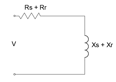
Induction Motor Simplified Model
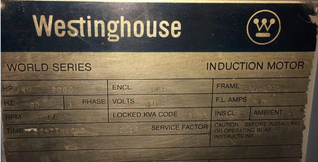
Motor Name Plate Data
Motor Starting Voltage Drop Calculation
Consider a motor connected to the utility supply through a transformer as shown. Xt is the transformer leakage reactance and XLR is the locked rotor reactance of the motor. Since many motors windings are connected in delta, it is important to convert the reactance to its equivalent wye. This value can also be calculated using the locked rotor KVA. Motor starting current analysis assumes balanced conditions and hence only positive sequence impedances are used. The electric utility system impedance is given as X1.
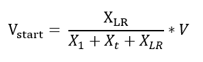
The lowest voltage during motor starting can be calculated using:
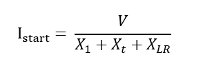
The motor starting current can be calculated using:
Motor Starting Power Factor Calculation
For estimating the motor starting power factor, the resistive component of the locked rotor impedance should, be included.
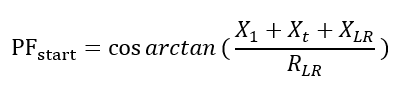
The power factor calculated above is the motor locked rotor power factor or the motor starting power factor. Typical motor starting power factor is 10% – 30%.
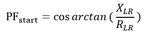
If the value of utility impedance (X1) and transformer leakage reactance (Xt) is not available, the approximate starting power factor can be calculated using:
Using NEMA Code Letter for Estimating Voltage Sag and Starting Current
Often times, the utility impedance may not be available for calculation. The project may be in the design phase or simply the information may not exist. In these cases, using the NEMA code letter that is stamped on the motor can be used to estimate the locked rotor motor starting current of the motor.
The motor starting voltage drop may be similarly calculated. The impedance of the transformer that feeds the motor is usually available and this information can use used to calculate the starting voltage.
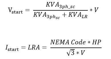
where LRA stands for Locked Rotor Ampere of the motor.
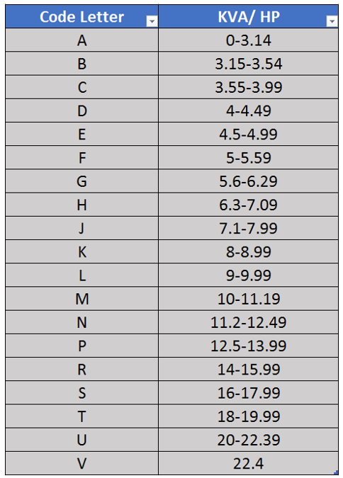
NEMA Code Letter
The following calculator can be used to calculate the motor starting voltage drop and starting current using infinite source assumption. Starting current of induction motor calculation uses actual motor name plate data and system impedance data.
If the NEMA code letter is not known, but the motor starting current is known then using the starting current equation above the approximate NEMA code letter can be derived.
Effect of utility short circuit capacity on the motor starting voltage sag
In the above discussion, the utility source impedance is neglected. It is usually ok to do that especially if there is a transformer on the supply side of the transformer. The source impedance will be dominated by the transformer impedance and neglecting the utility source impedance usually introduce only minor errors.
If the source impedance is high (a weak utility system or a generator), or when the motor is fed directly from the utility supply, including the source impedance will give more accurate voltage sag magnitudes.
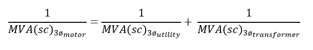
The three-phase short-circuit capacity at the motor terminals can be calculated using:
The voltage drop during motor starting can be calculated using:
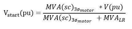
Where,
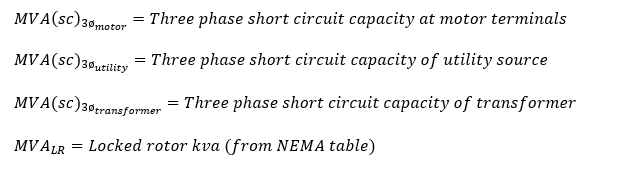
Use this calculator to calculate motor starting voltage drop considering utility source impedance.
If the NEMA code letter is not known, but the motor starting current is known then using the starting current equation above the approximate NEMA code letter can be derived.
Additional Reading:
Transformer Impedance: Why is impedance in percentage?
Source impedance calculation in power system
Reference: Fundamentals of Electric Power Quality, Surya Santoso